Project Offgrid - Garage Build, Part 2
In the last part, most of the trench work was buried back up and the GridBoss and FlexBoss21 were mounted on the wall. This post picks up where that left off — getting the remaining panels mounted, running EMT, terminating cable, and getting temporary power back into the garage so I can actually finish the job.
Garage Progress
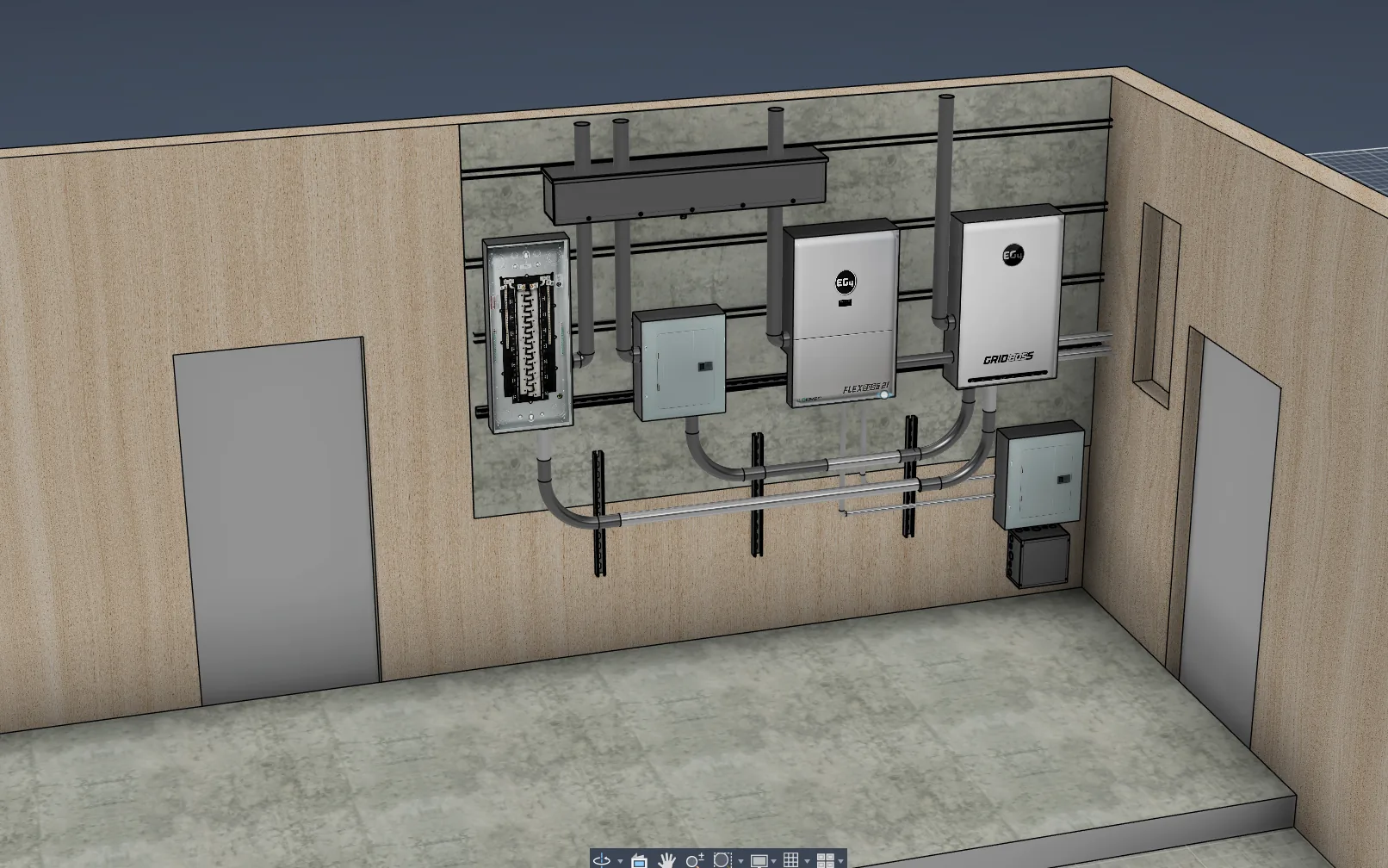
Here is the original drawing —
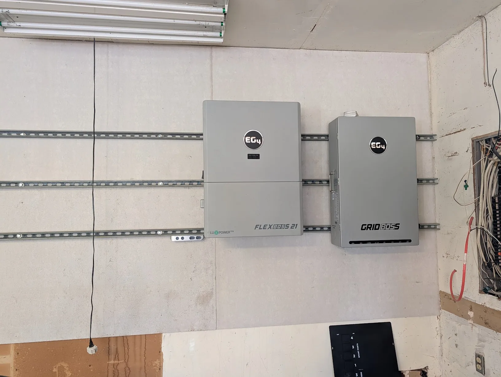
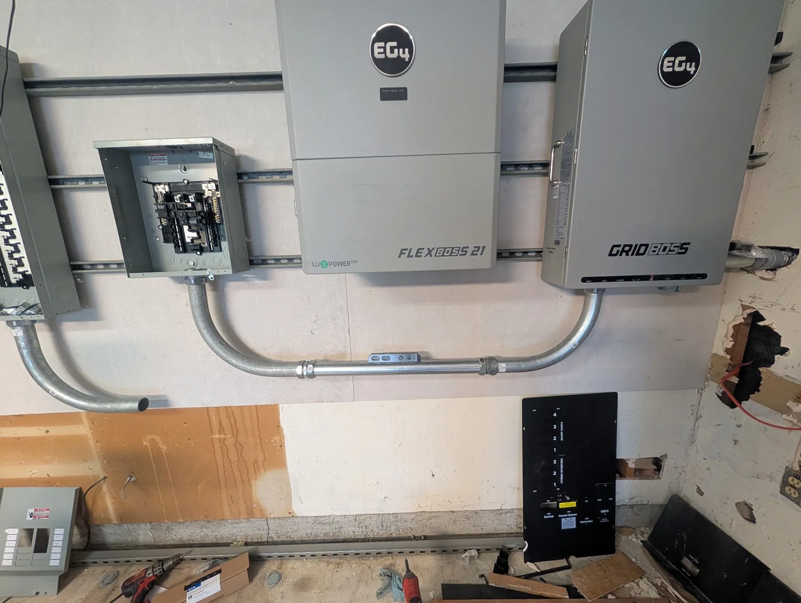
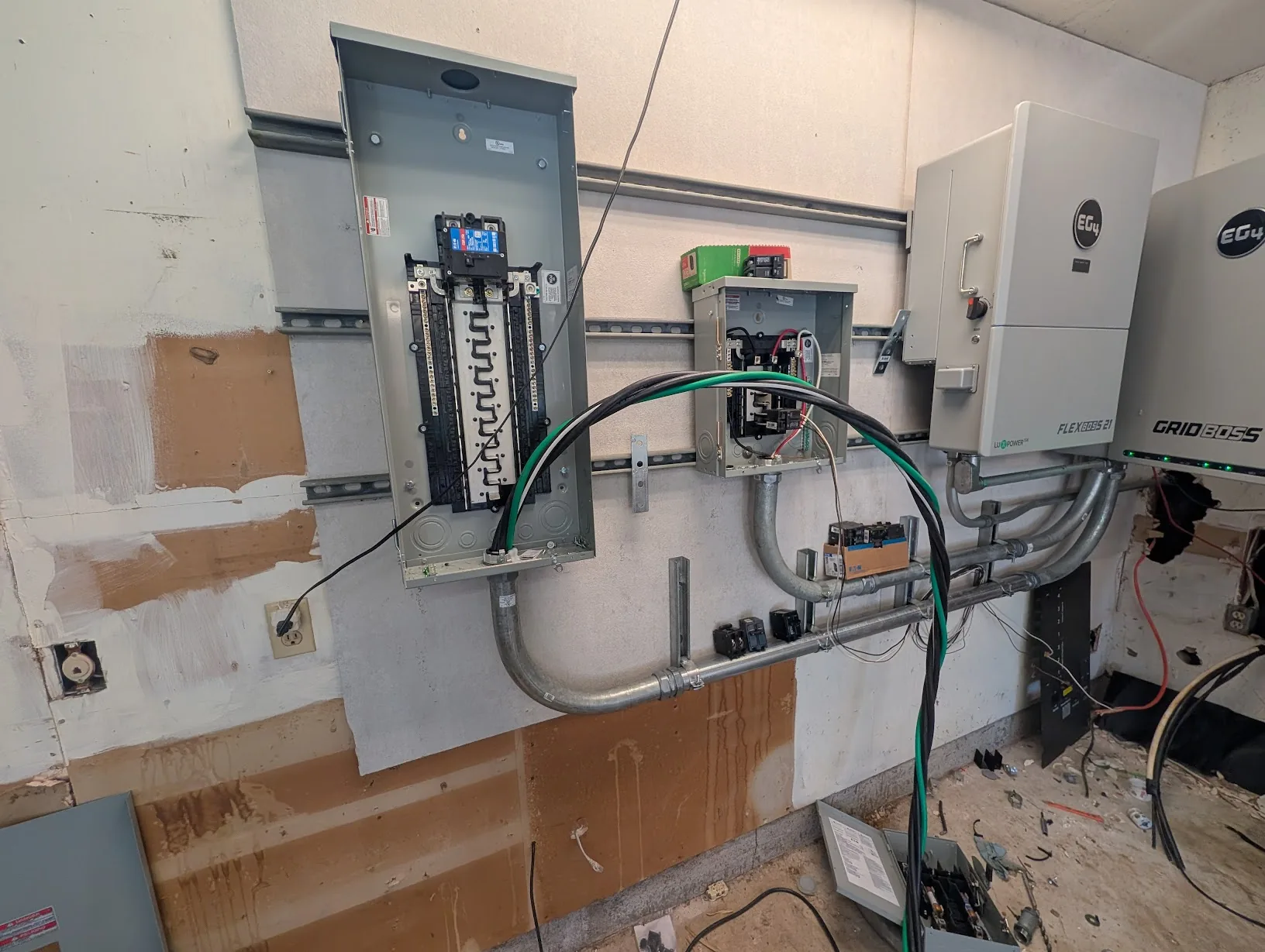
And here is where the last post left off:
Its time to get the other panels mounted, and get cable pulled.
Mounting Panels
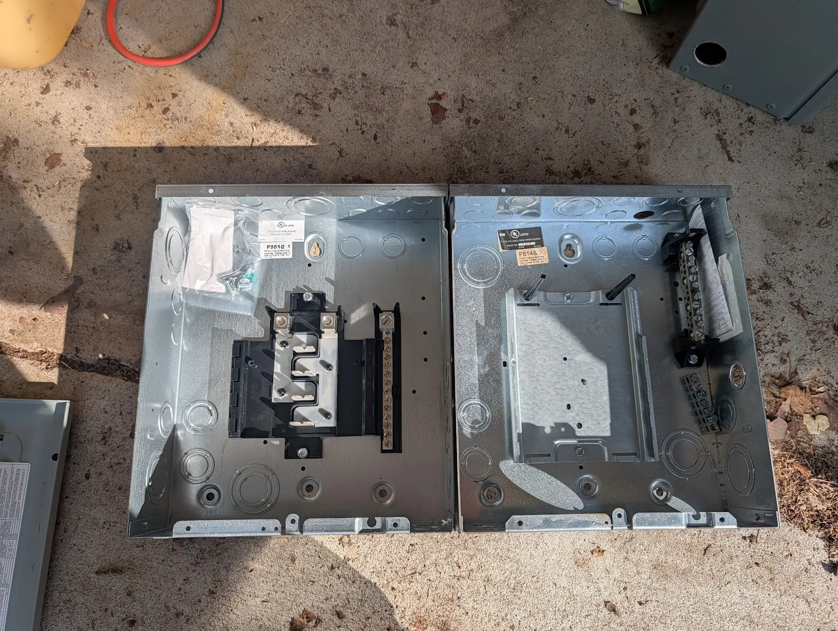
Step 1 — acquire new panels.
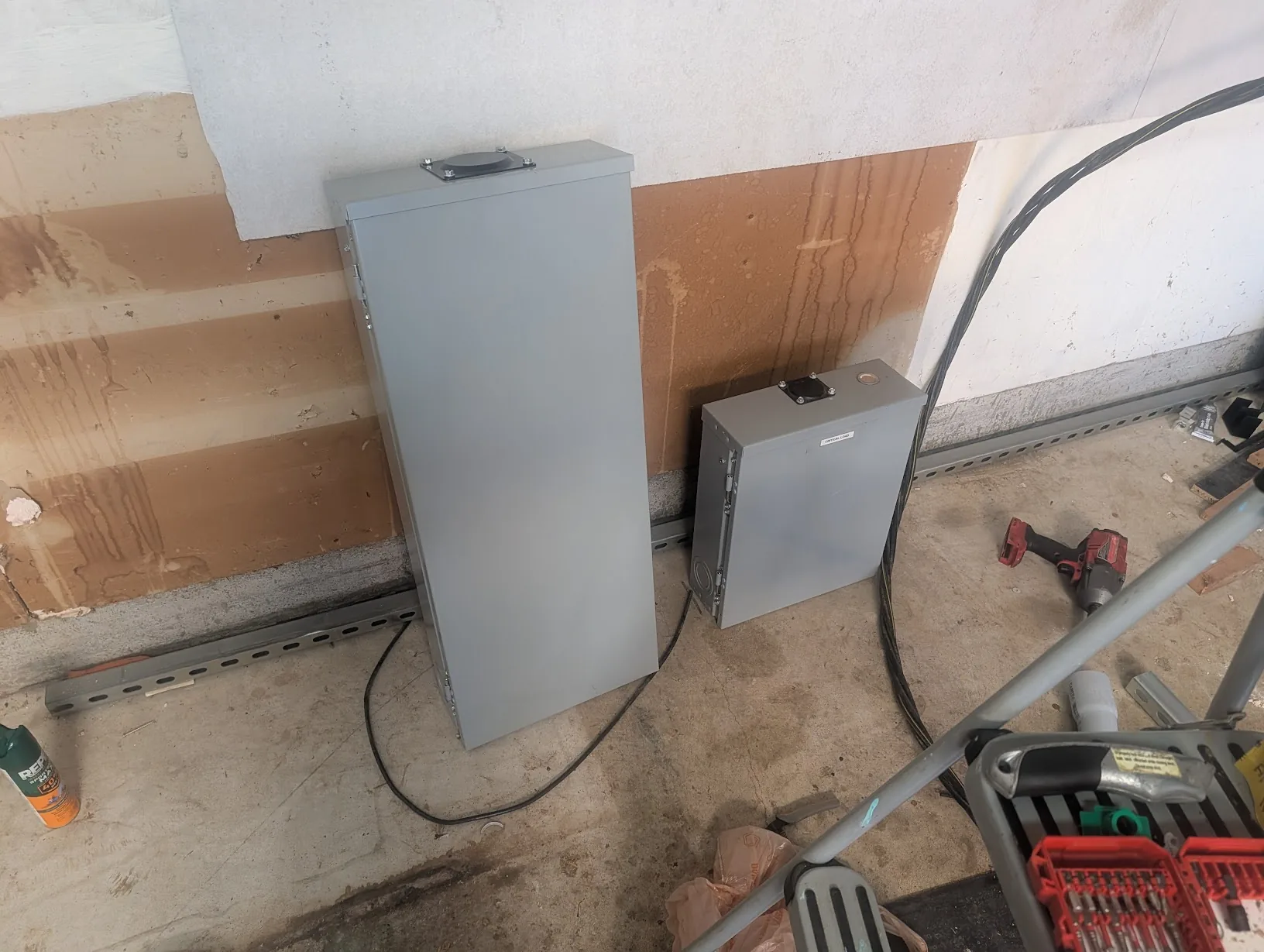
The left panel is an Eaton BR 200A outdoor 60-circuit load center with plug-on neutral.
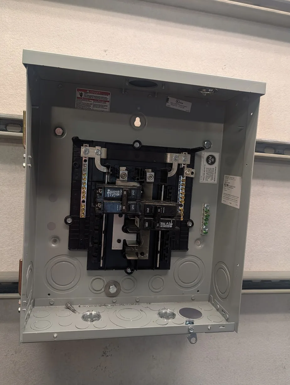
The smaller panel on the right is the old critical-loads panel from my original solar project. It is a 12-slot, 125A outdoor-rated panel.
Mounting Main Panel
Looking at the main panel, it already had holes for screws.
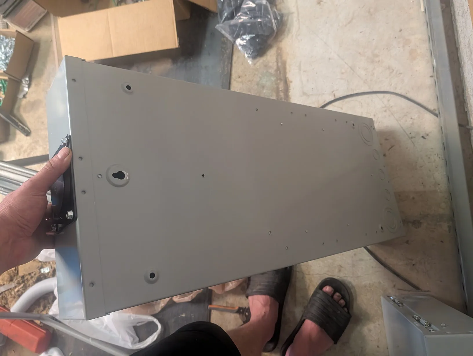
But they were slightly too small for the mounting hardware I was using.
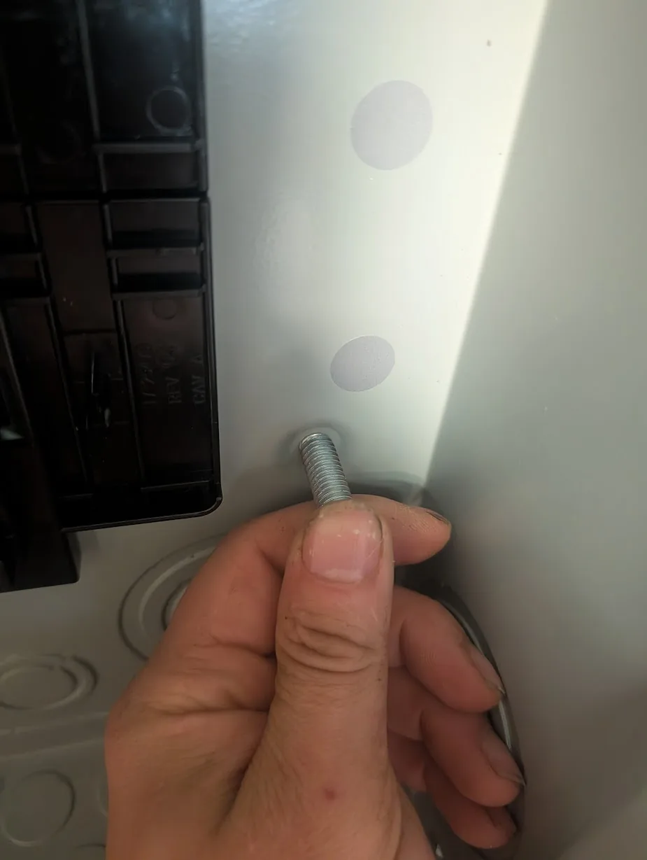
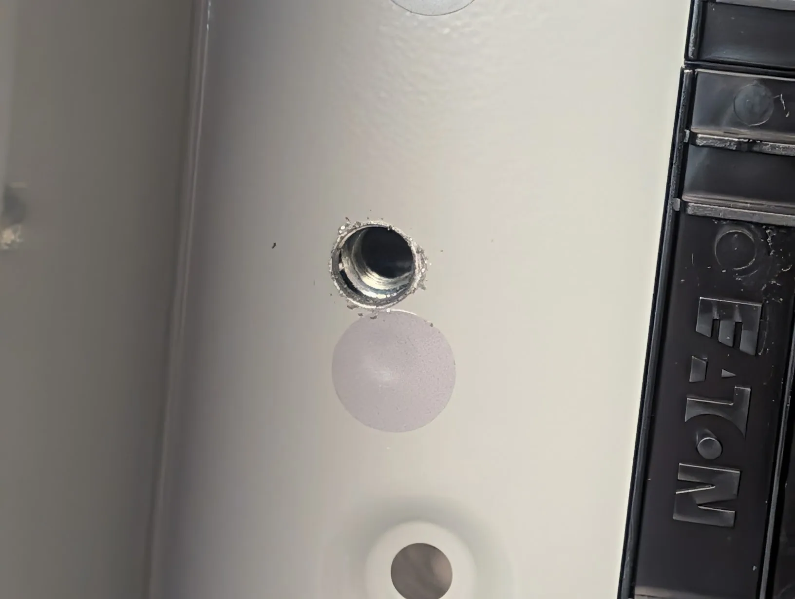
A quick pass with a step bit fixes that issue.
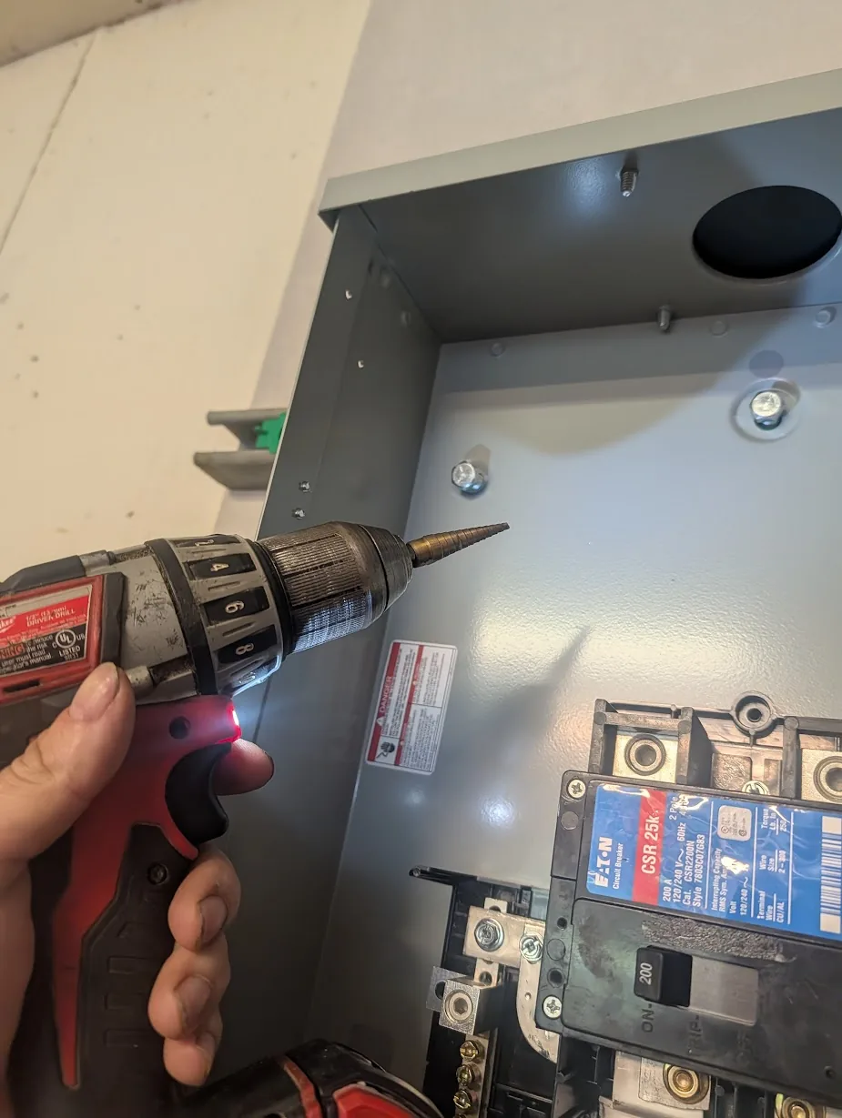
Afterwards, I needed to mount the bottom. BUT, there aren't any holes intersecting with my existing unistrut. Shame.
With a bit of help from the drill, I landed a few perfectly spaced holes.
And now you can do pull-ups on this panel with absolutely zero concerns of it coming off of the wall. Seriously, I did.
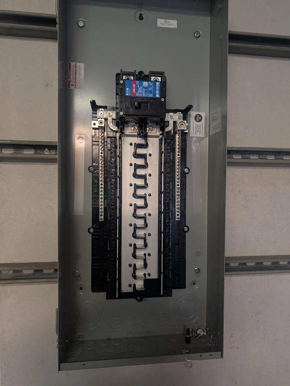
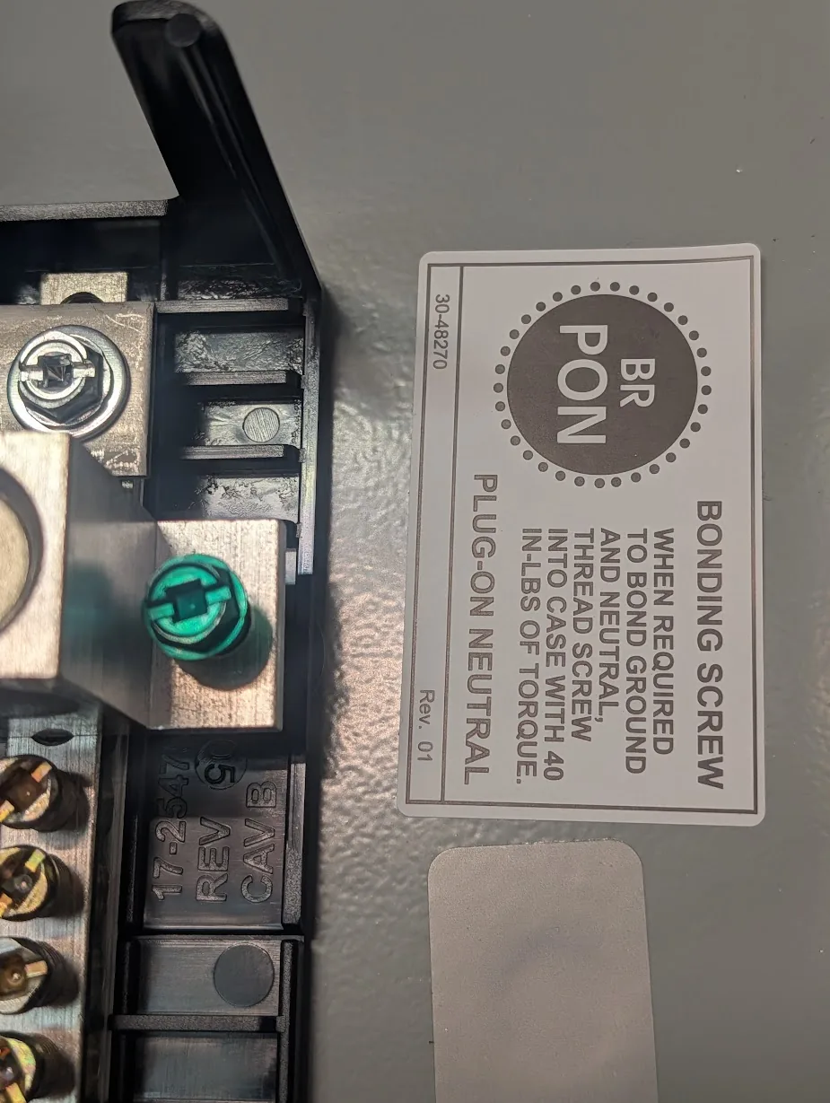
Do make sure to remove the bonding screw...... unless this is intended to be your bonding location.
Mounting Subpanel
For the subpanel, I used the existing two holes near the top.
Then drilled a single hole in roughly the middle to mount the bottom. I added a washer to make sure there wouldn't be any issues with the screw pulling through.
And of course, I did verify I can successfully use the panel as gym equipment.
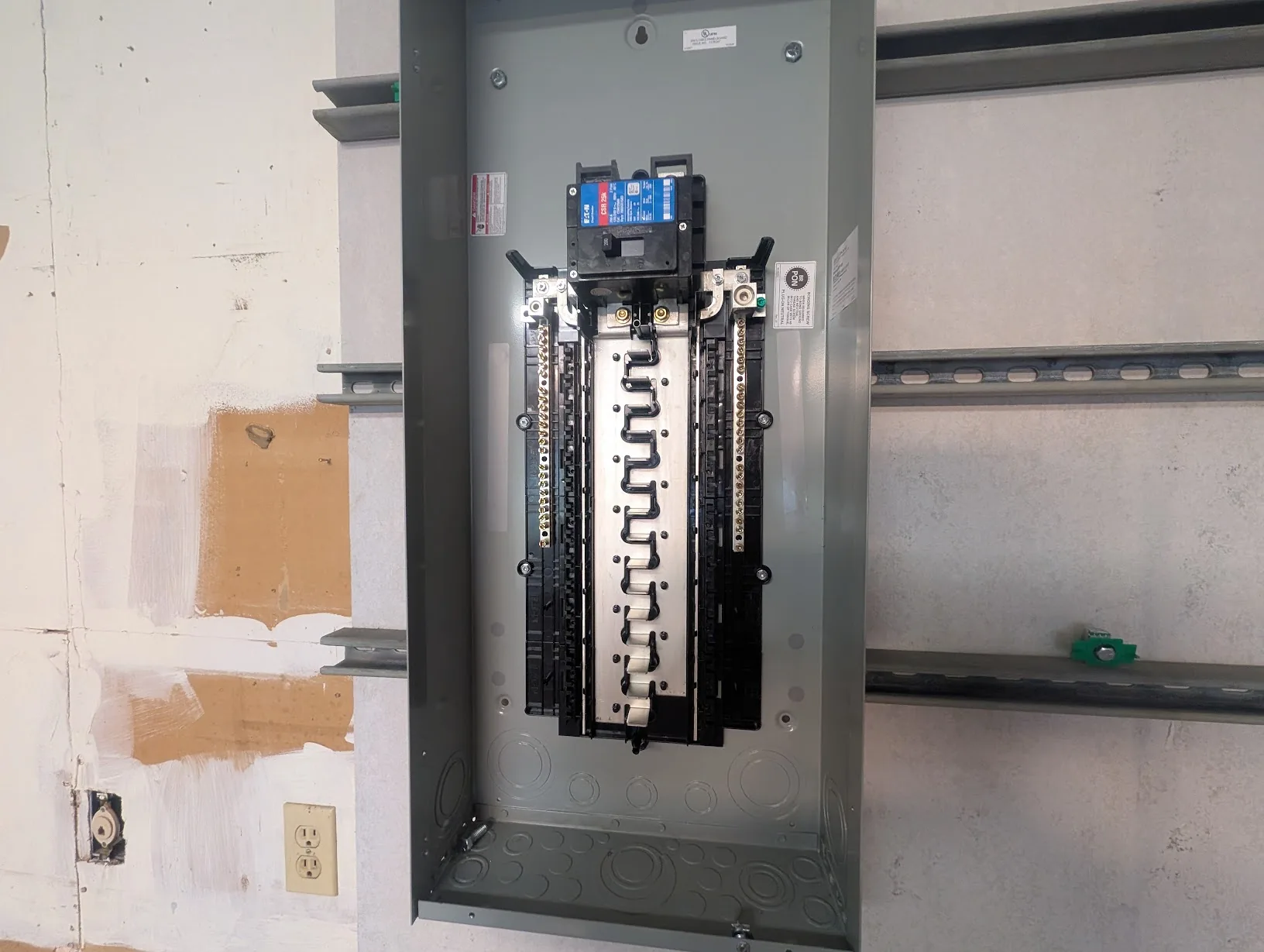
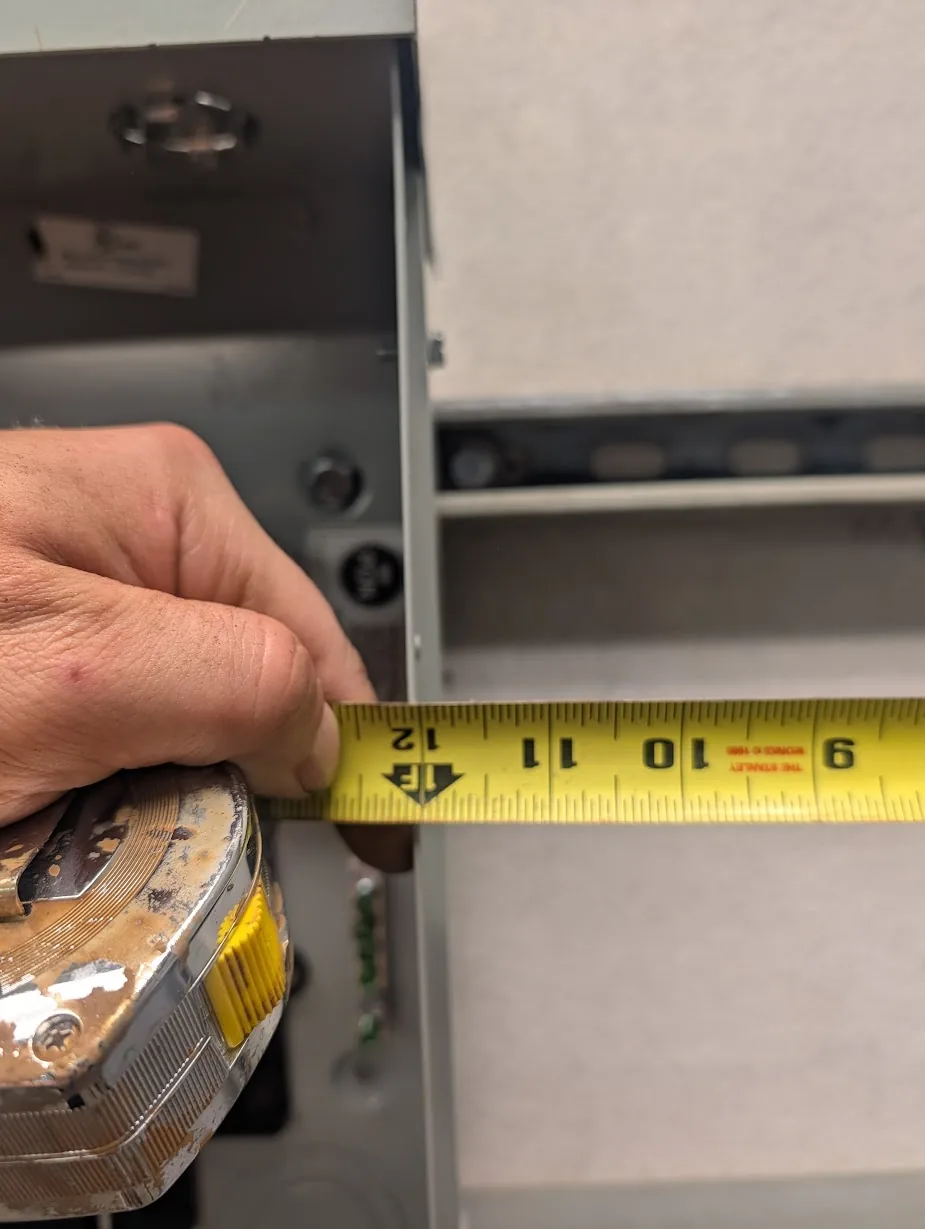
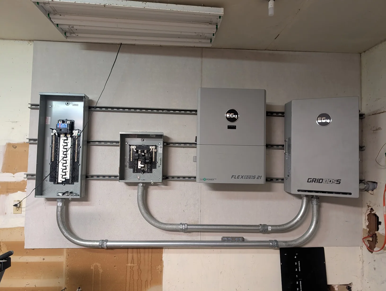
Per my drawing, spacing is exactly 1ft between all panels.
With that, all of the panels are now mounted.
Connecting Garage Power
Ok, remember that part where I ran a trench through my garage's power line? Well, I need power in my garage to run tools, welders, etc. So before running all of the conduit, it is time to get power connected up in the garage.
New panel in shed
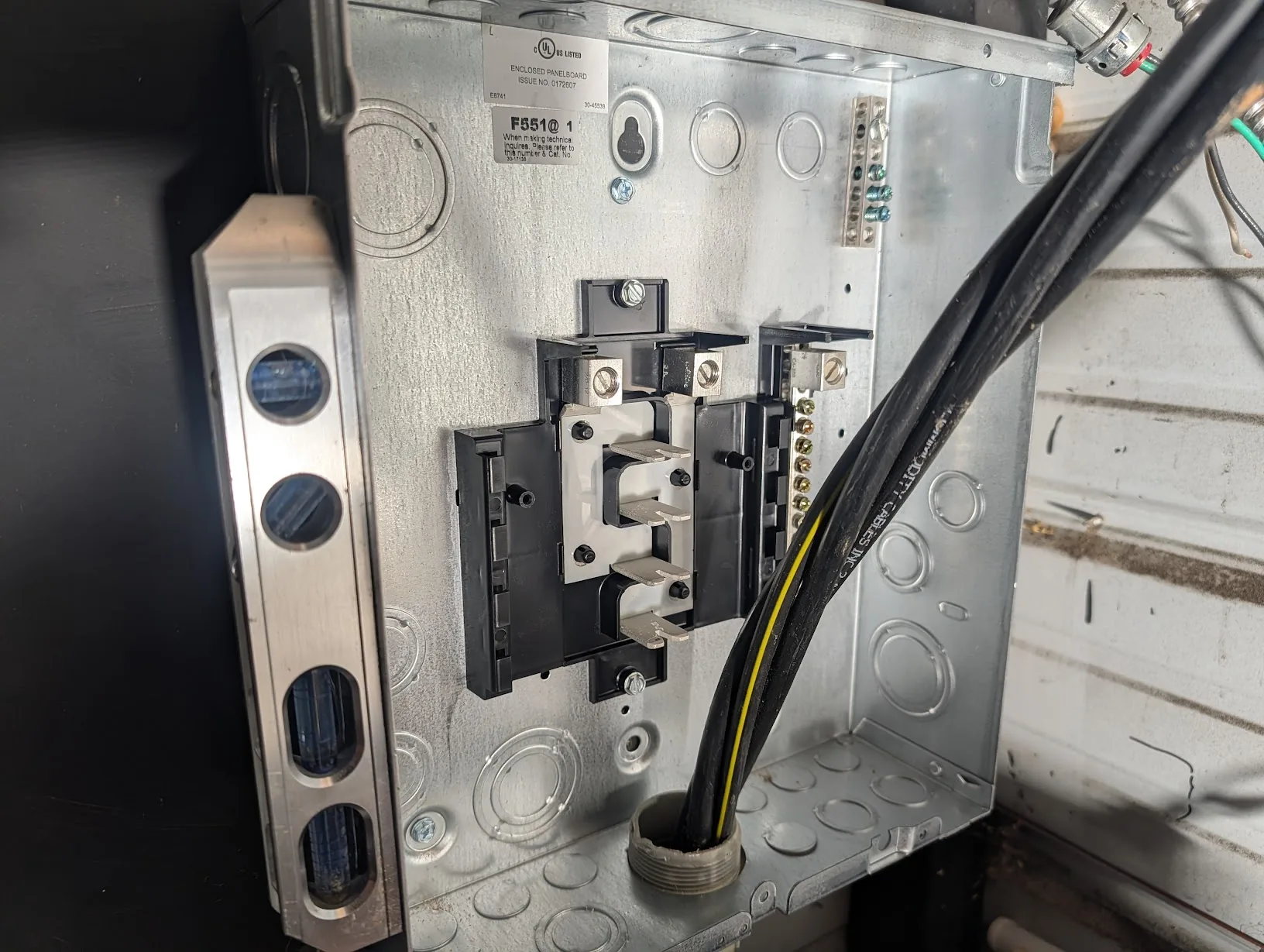
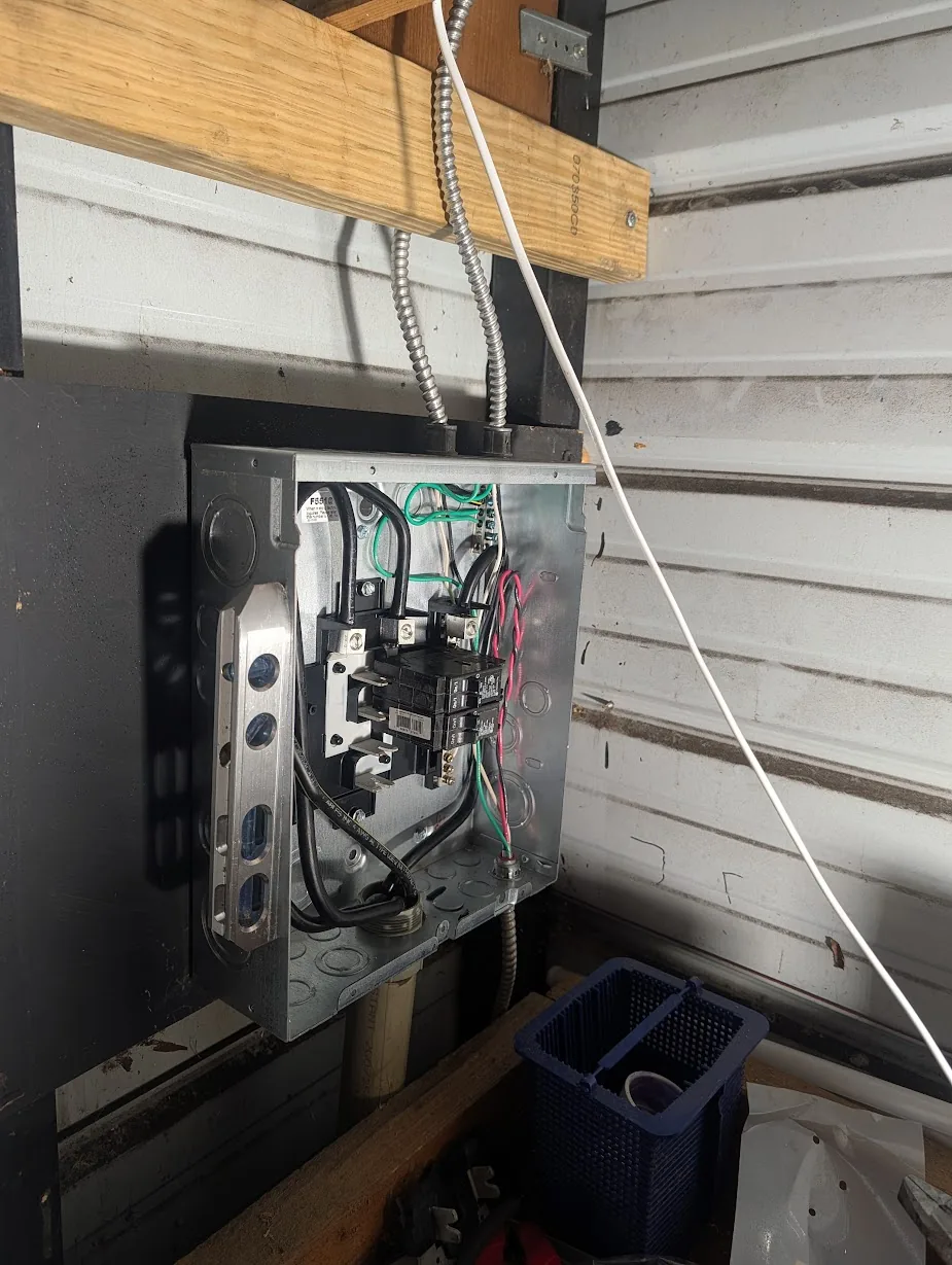
The panel in the shed was destroyed a bit after the trencher forcefully pulled the cable out.
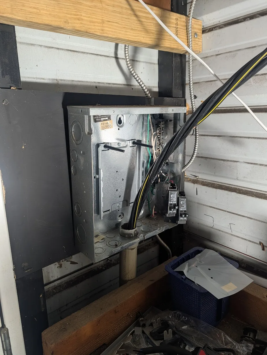
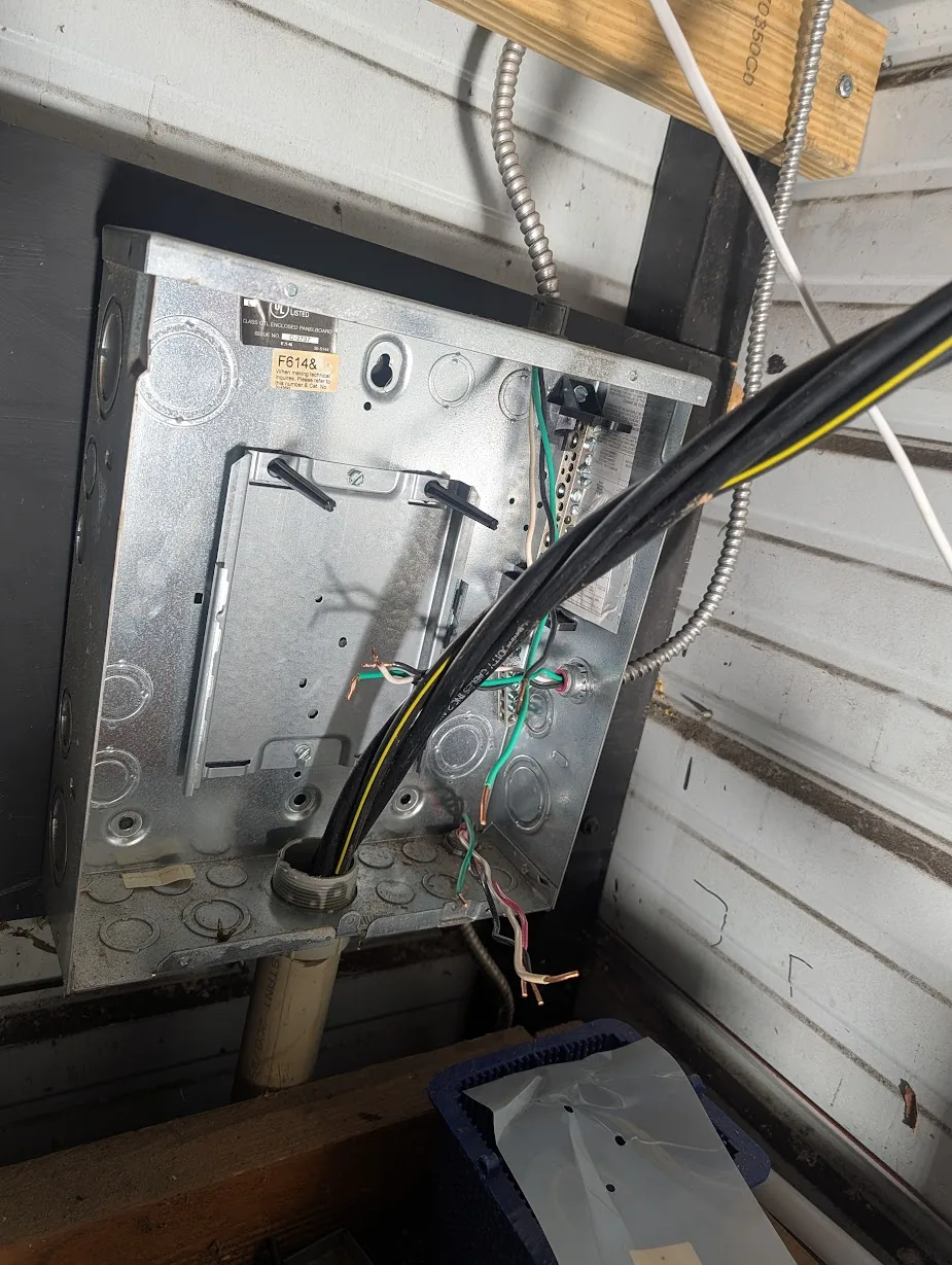
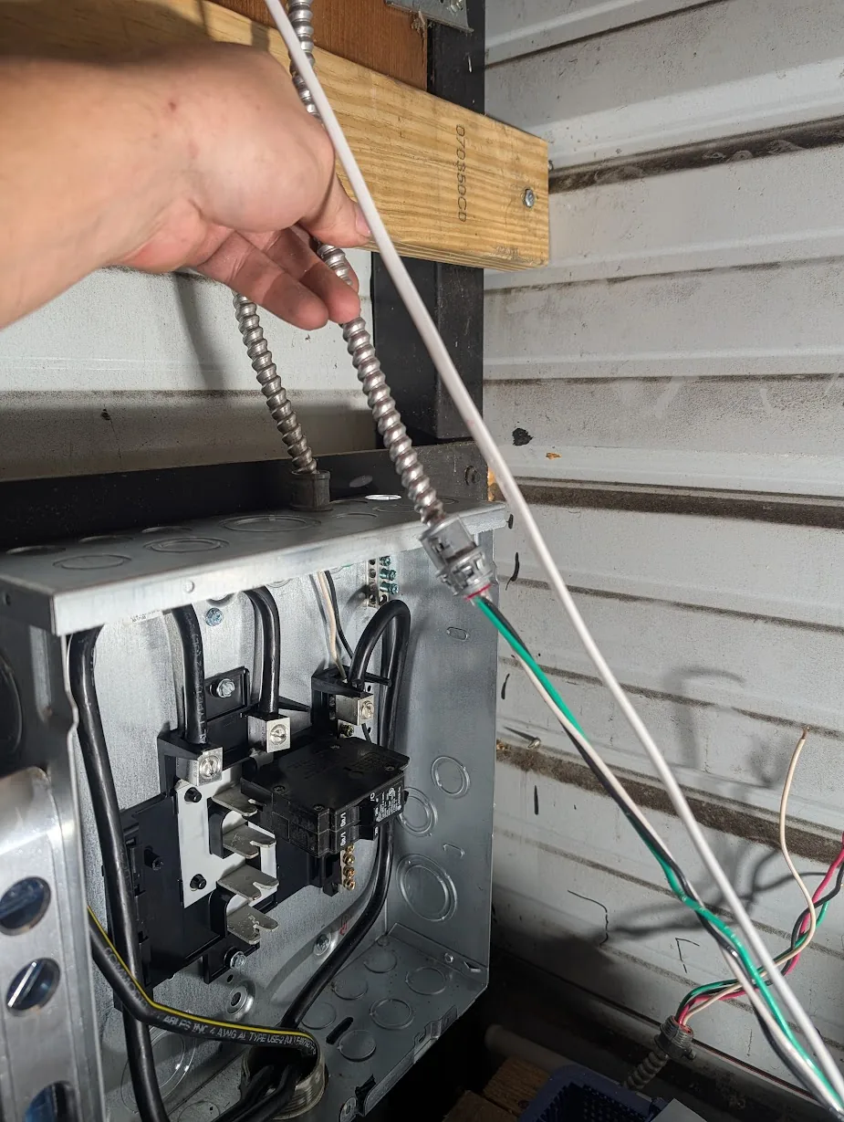
Step 1 — disconnect everything.
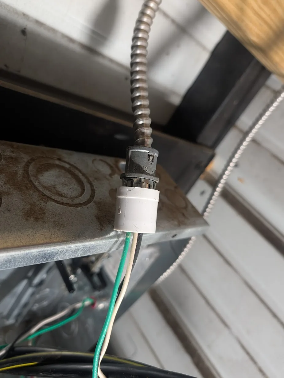
I found a small pipe fitting helps to release these locking MC connectors.
Out with the old panel.
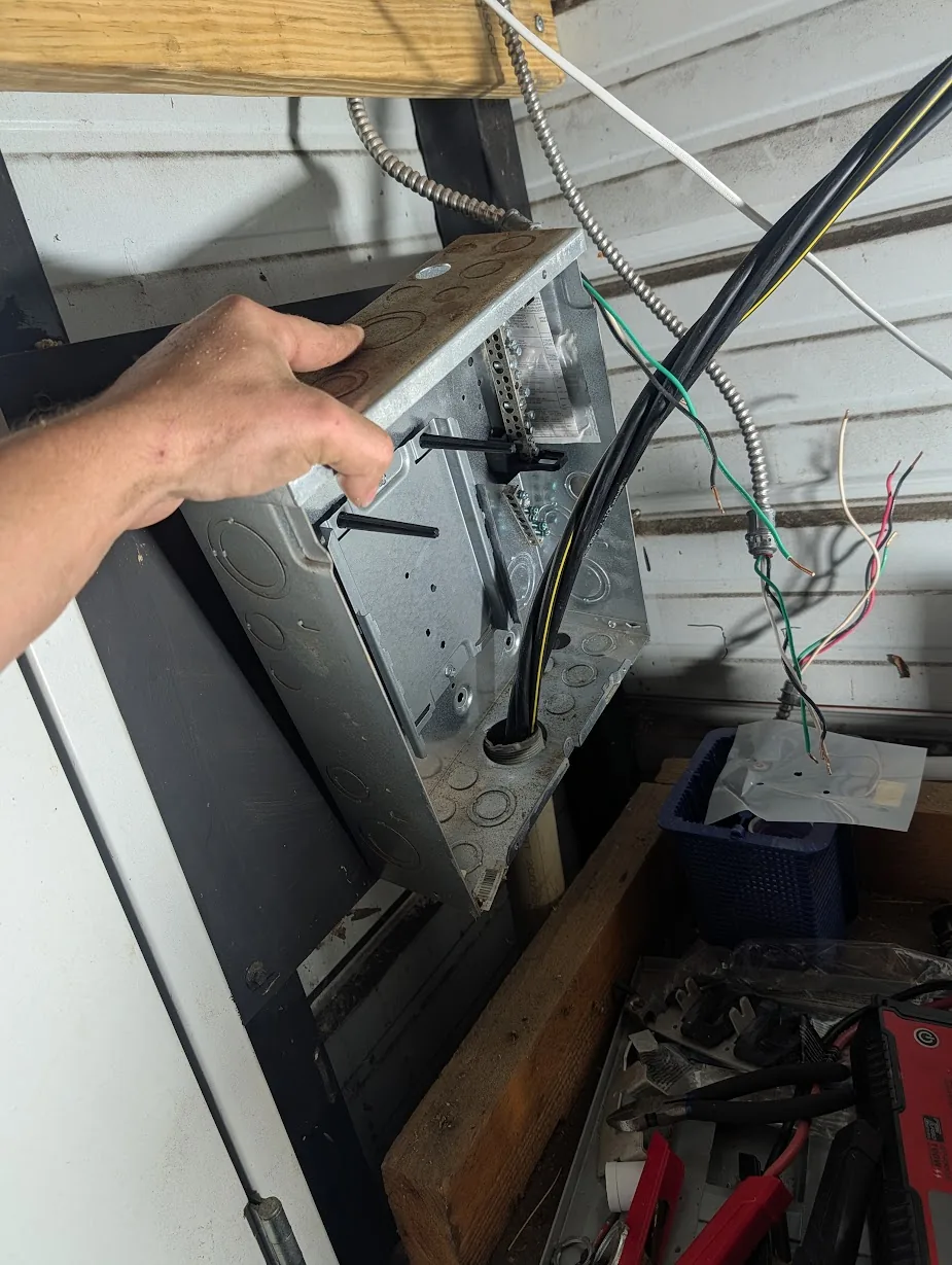
Comparing with the new panel (left).
Mount the new panel. Use screws to secure.
Bend the 2/2/2/4 to fit.
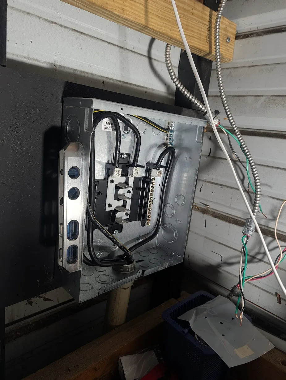
Start opening knockouts and installing connectors.
Wire everything up.
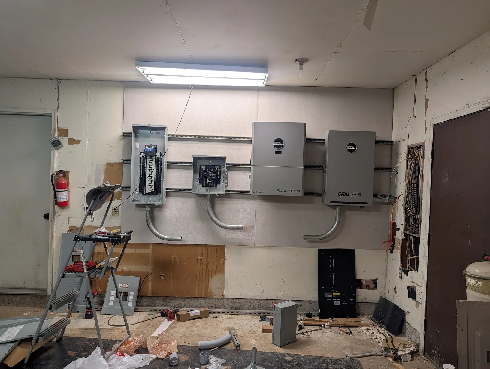
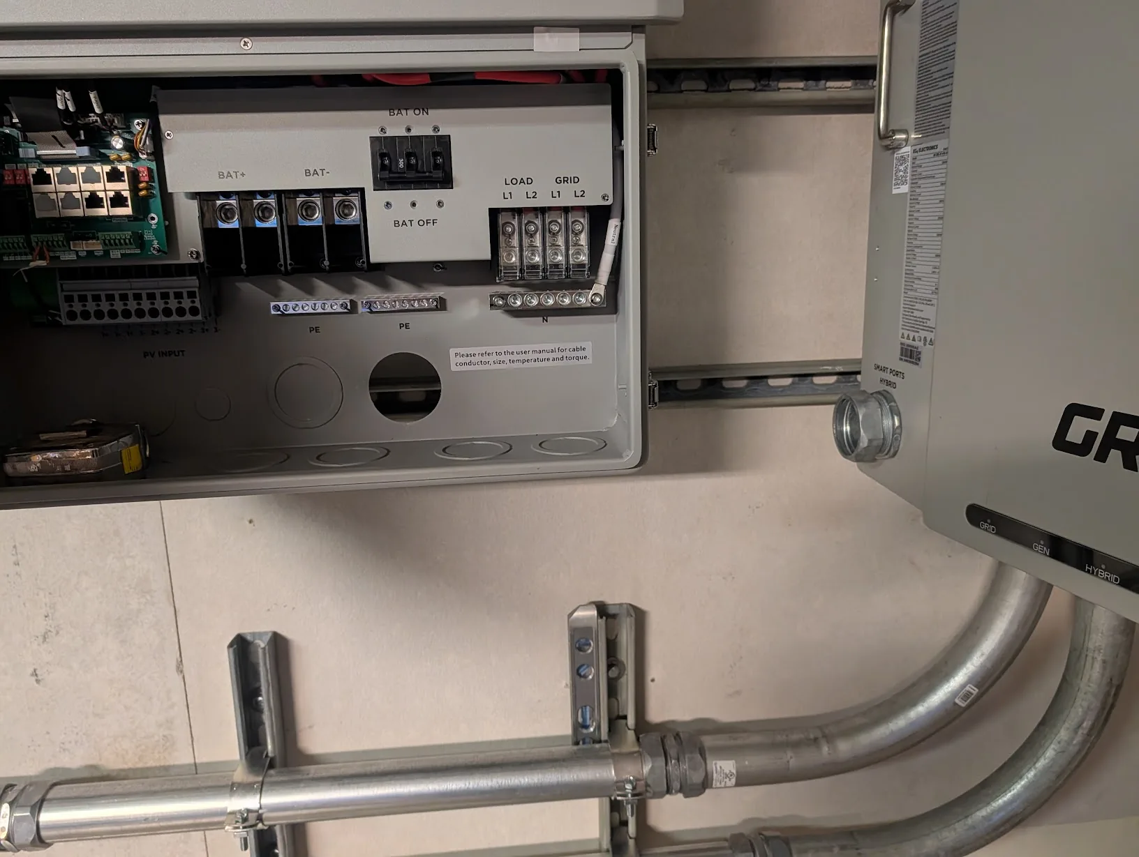
Wiring up the GridBoss
Since the 2/2/2/4 cable has already been pulled into the GridBoss, I just need to terminate it.
I will be using the #1 smart port for my shop's electrical connection since it is rated for a 125A breaker. The #2 port is rated for 90A, and #3 and #4 are only rated for 60A.
After a bit of work, the shop feeder was terminated.
A 100A breaker is used for the time being.
For the time being, I used a temporary connection back to a 60A breaker on the existing panel. (Ignore the conduit — that is in the next section.)
And.... let there be light. I can charge my Milwaukee batteries again!
Back to working on the garage.
Running Conduit
Time to start the fun part — installing conduit!
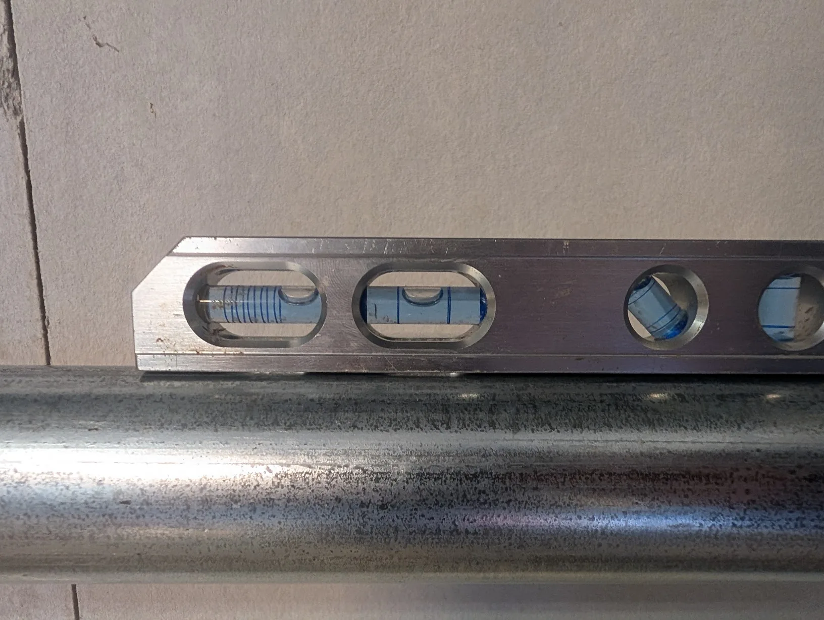
I started by installing the 90-degree sweeps in the main locations.
Then I cut the first piece of conduit. I trimmed a few inches off of the elbow to get it perfectly level.
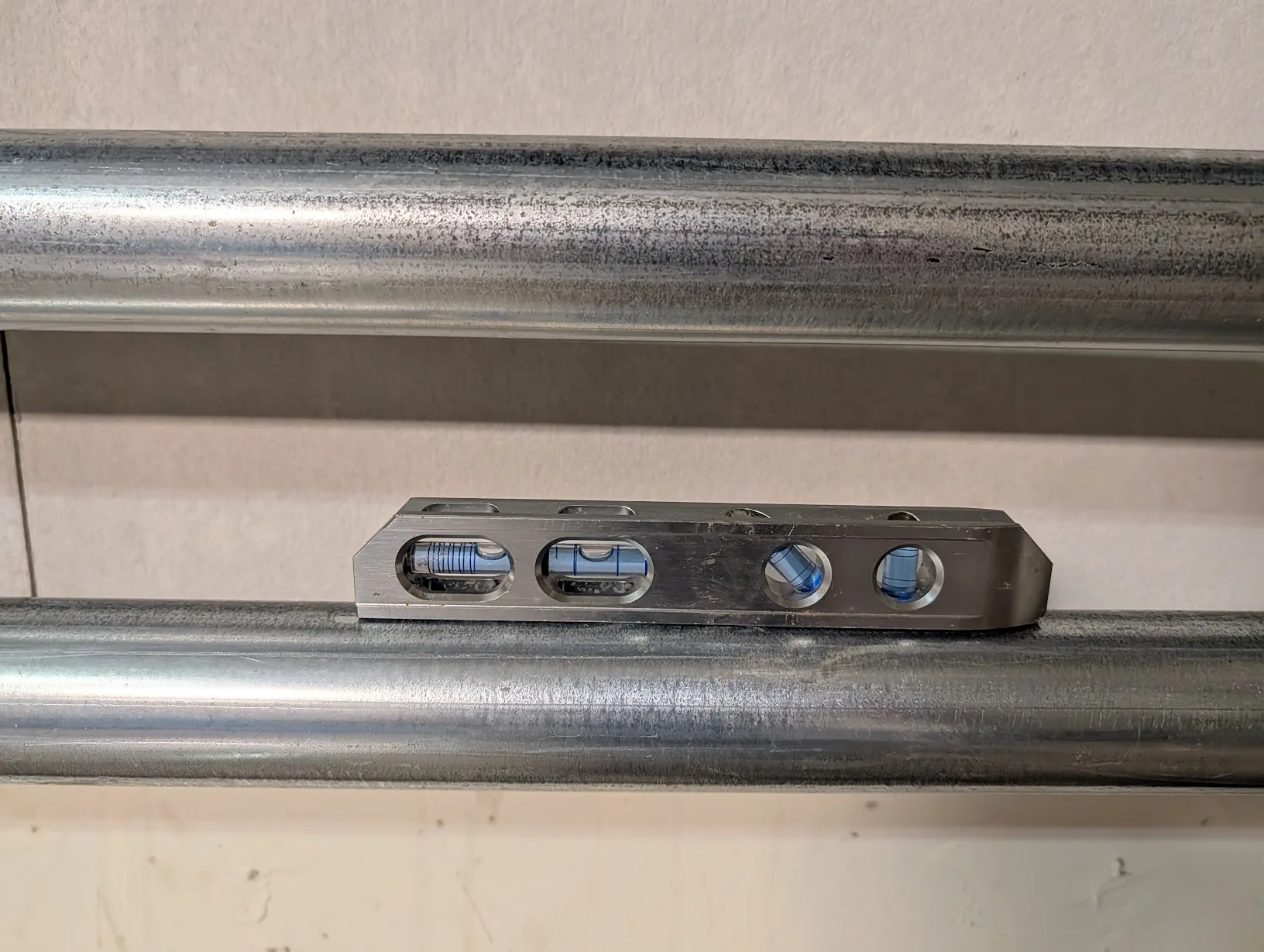
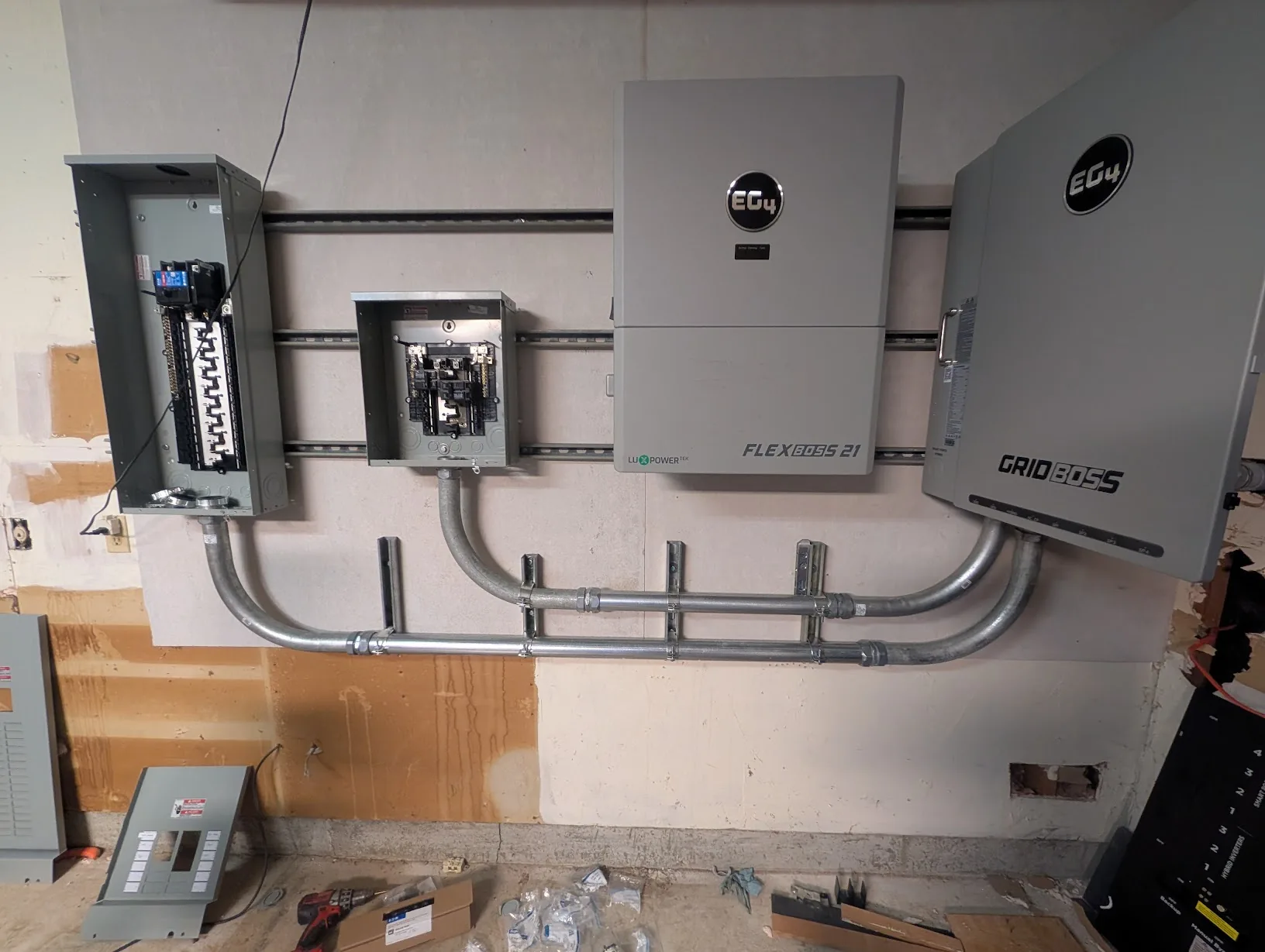
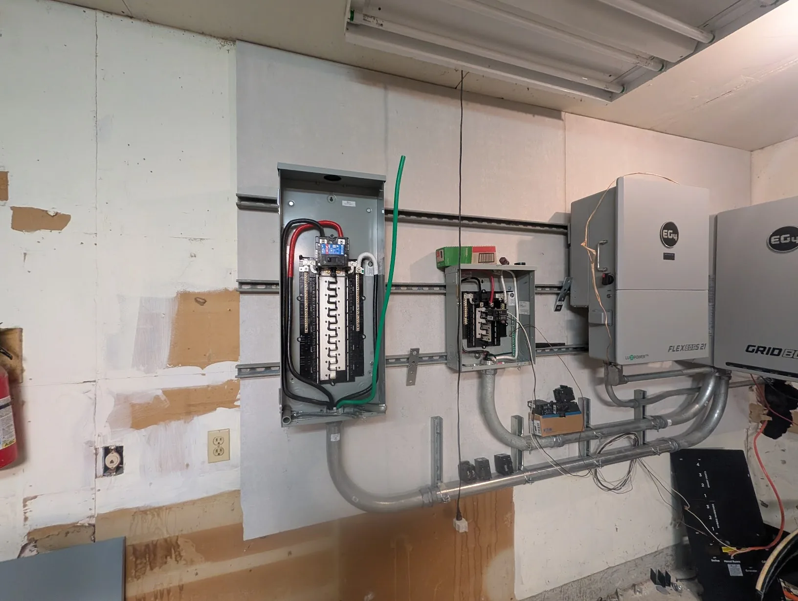
Then I did the same with the conduit between the main panel and GridBoss.
Starting to look a little bit better, eh?
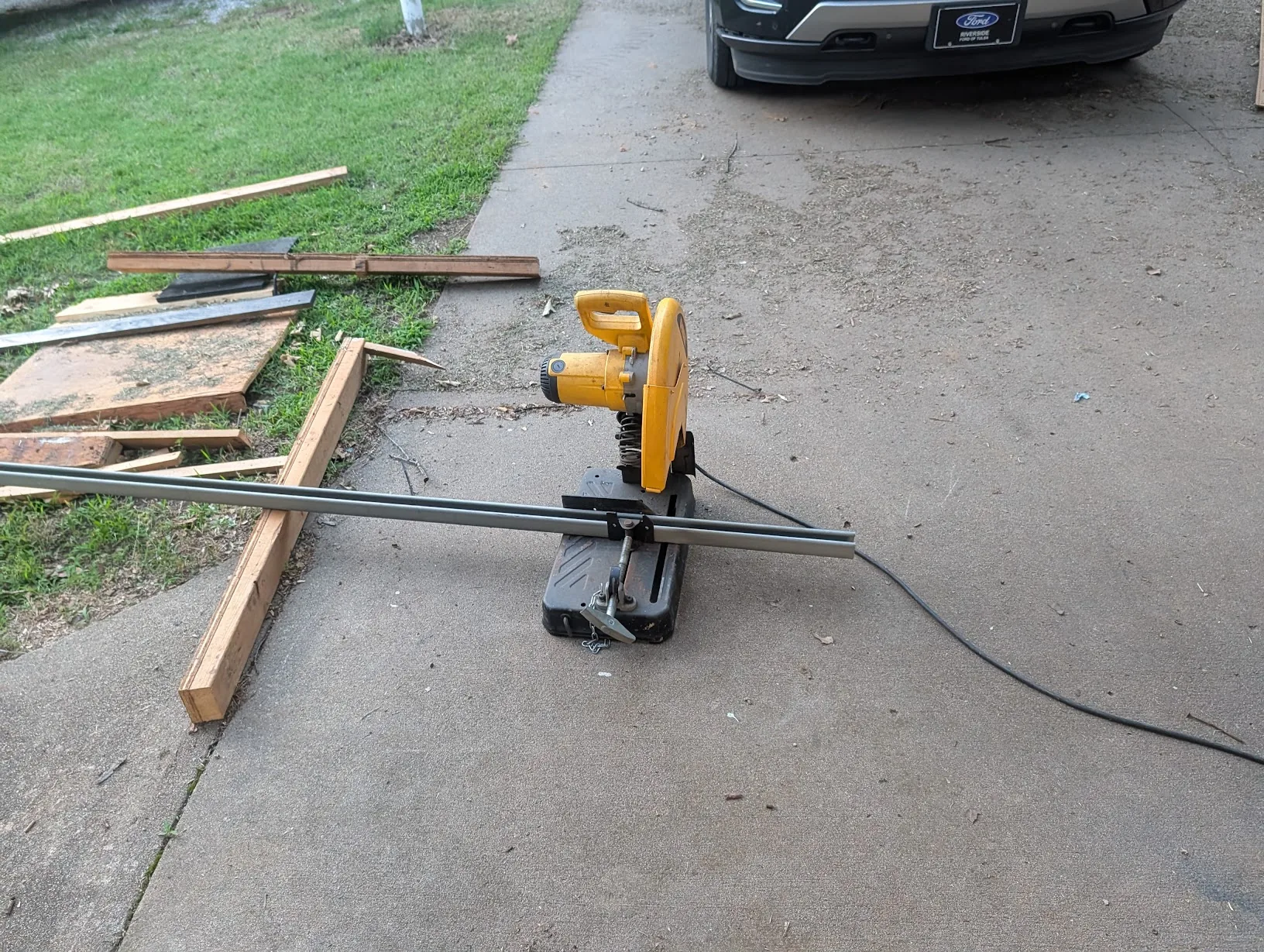
I needed a few short pieces of unistrut for securing the conduit to the wall. I used my Dewalt chopsaw for the task.
And — the installed mounting brackets for the conduit, back to the unistrut.
Between GridBoss and FlexBoss
Since the FlexBoss was mounted slightly higher than the GridBoss, this made the process slightly more challenging to run nice, pretty conduit. After looking at the options, I decided to run the main conduit in through the rear.
I used a 45-degree PVC elbow just to vet the idea.
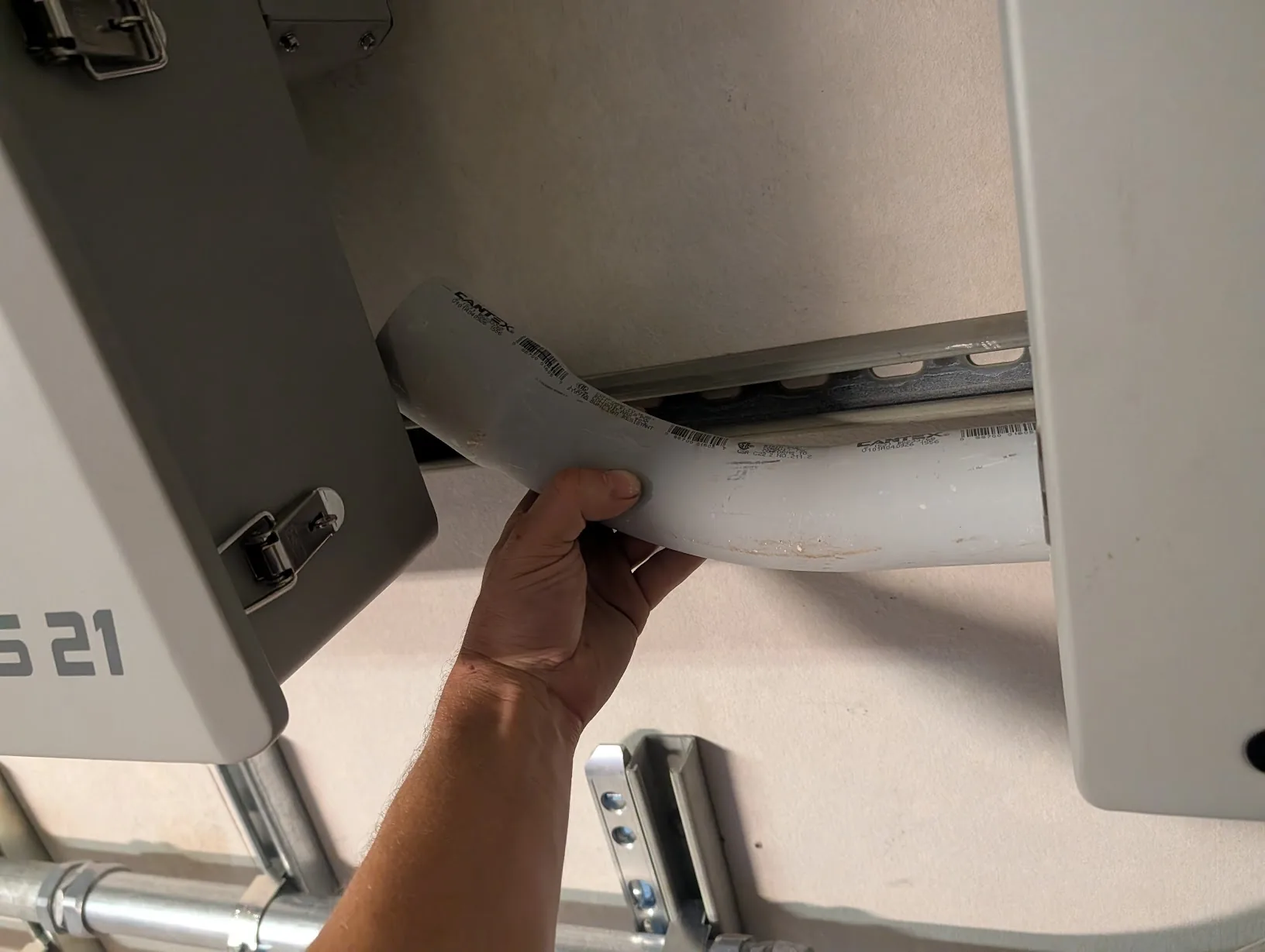
Then I measured to cut the real conduit.
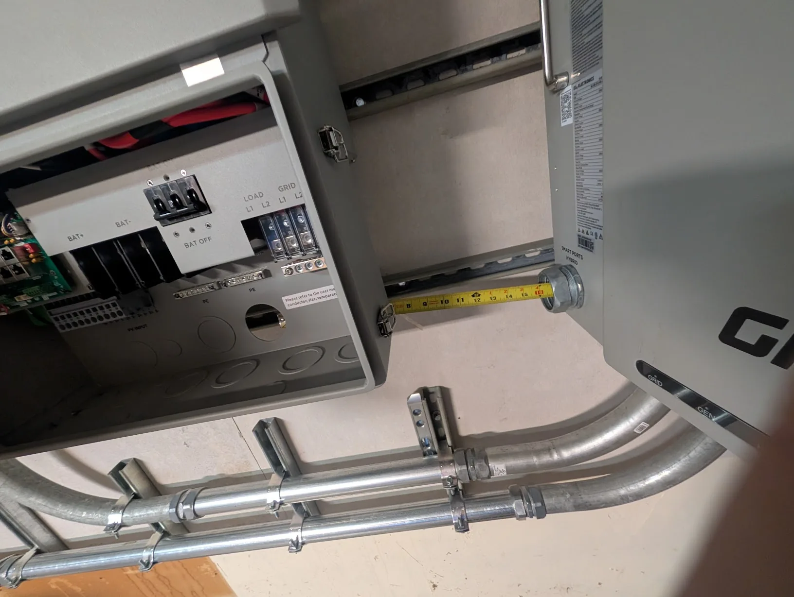
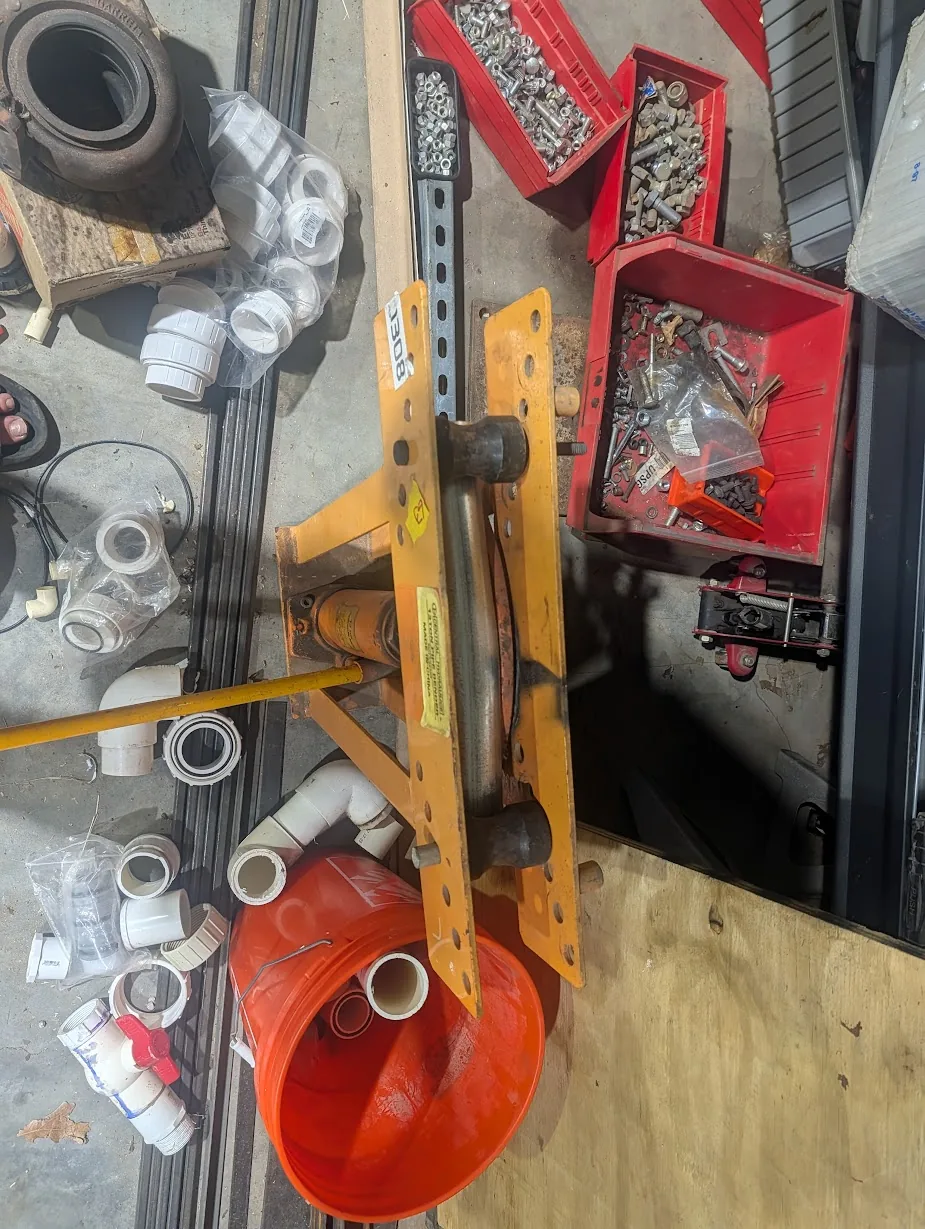
I used my pipe bender to put a SLIGHT angle on the new conduit.
Which lined up nearly perfectly.
Afterwards I installed the connectors and tightened everything down.
Pulling Cable
Cable Used
With all of the panels connected, it was time to start pulling some cable.
For the subpanel, which is behind a 100A breaker, I went with 2 AWG copper THHN, which is rated for 115A. I also used this cable for wiring the inverter.
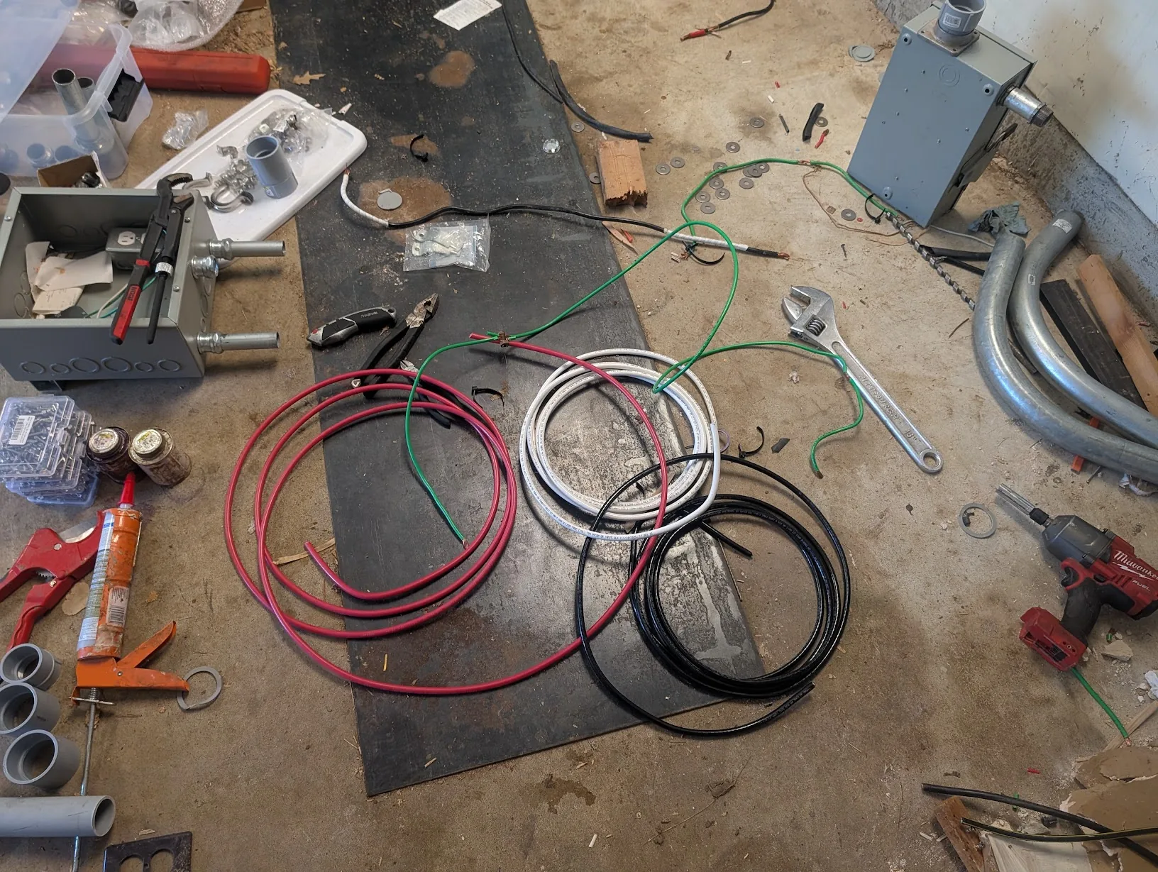
I ordered around 45 feet total (red, white & black).
Nassau - 2 AWG Copper THHN/THWN-2
Note — not affiliated with Nassau.
For the 200A main panel, I ordered 25ft of 4/0-4/0-2/0-4 feeder cable.
Nassau - 4/0-4/0-2/0-4 Aluminum Mobile Home Feeder Cable
While I vastly prefer using copper, aluminum saves a good chunk of money here.
Pulling Cable
For the most part, pulling the cable was not too bad. I used cable lube to make this job quite a bit easier.
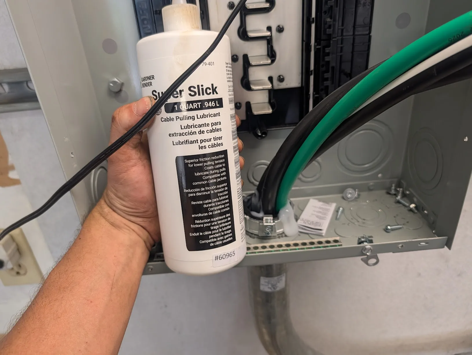
Amazon - Gardner Super-Slick Cable Lube1
After putting a good amount of lube into the conduit, even the massive 4/0 cable pulled pretty easily.
Aluminum conductors — use anti-oxidant
Since the 4/0 feeder is aluminum, the terminations need anti-oxidant compound (Noalox / Penetrox / equivalent) on the conductor strands before torquing them into the lugs. Bare aluminum oxidizes the moment it hits air, and that oxide layer is a resistor — the connection heats up, the lug loosens, and eventually you get a fire.
The fun part is getting the cable bent into place. That is a workout.
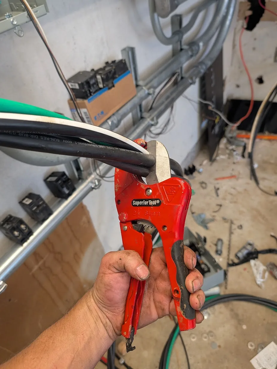
While my pipe cutter doesn't work the best for cutting pipe, it works extremely well for cutting through this thick cable.
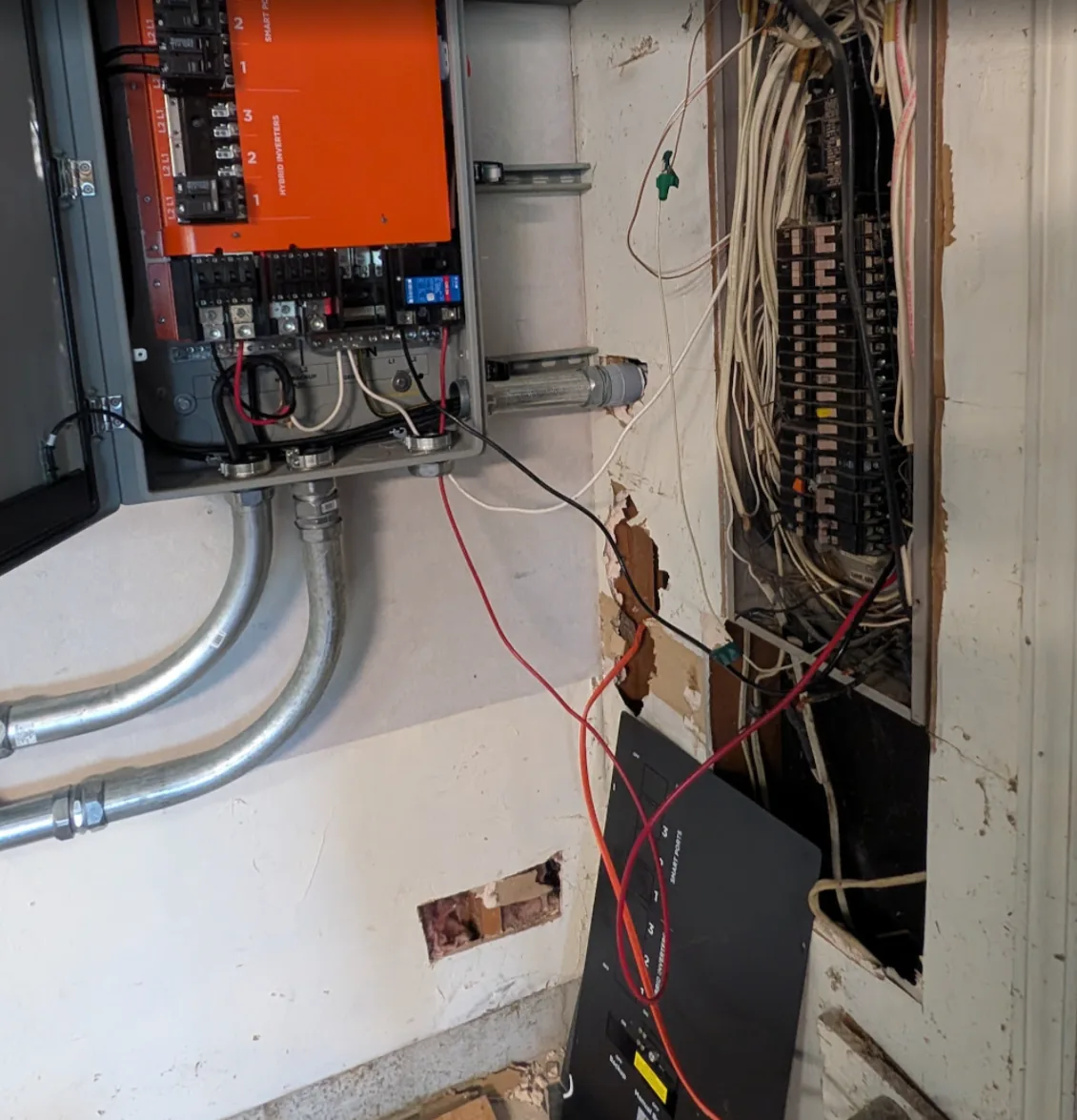
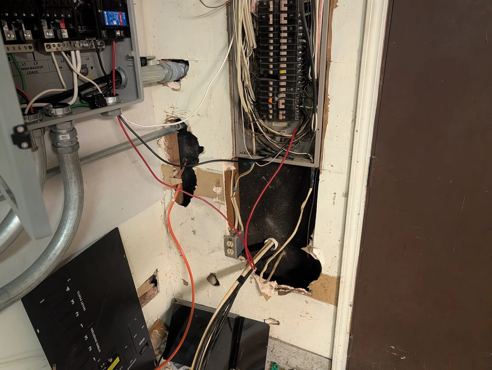
After getting mostly everything bent into place for the main panel and subpanel, it looked like this:
Info
Ignore the temporary circuit running to the subpanel — its powering the mini-split here in my office, since the old panel is out of room.
It will be cleaned up and done correctly soon enough.
I found a short section of PVC pipe and a big wrench helps to bend the cable better.
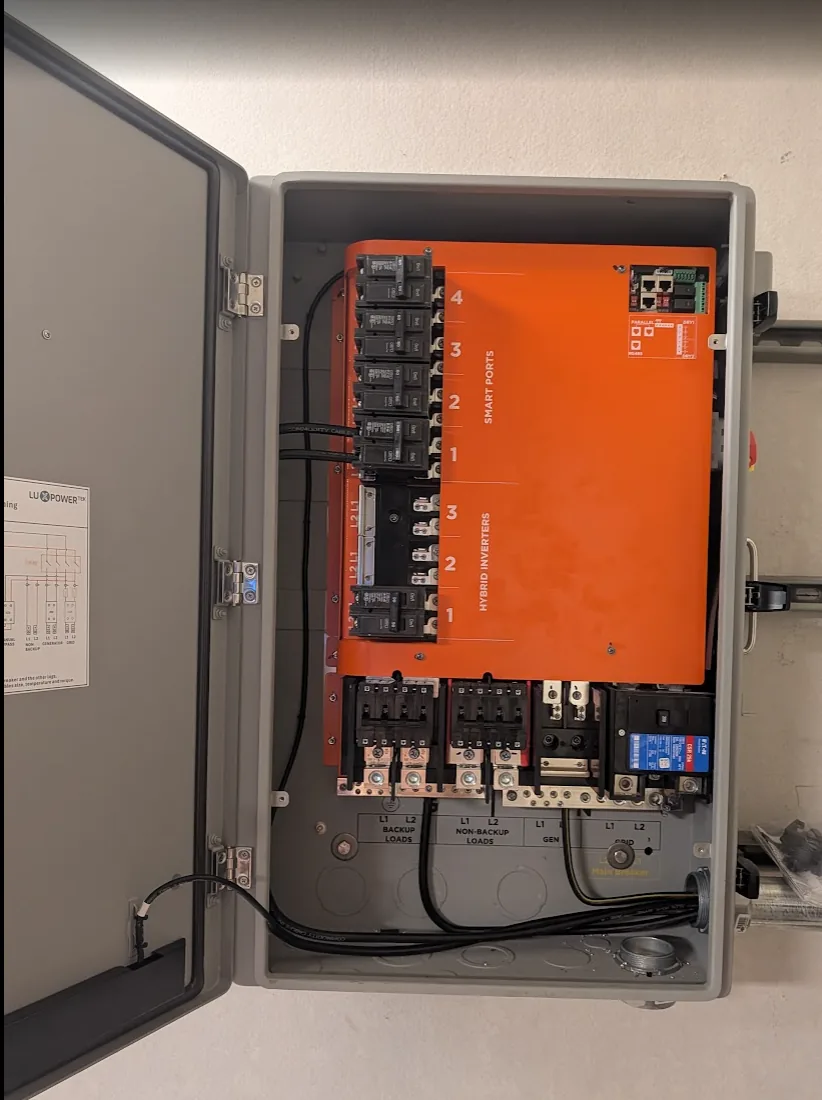
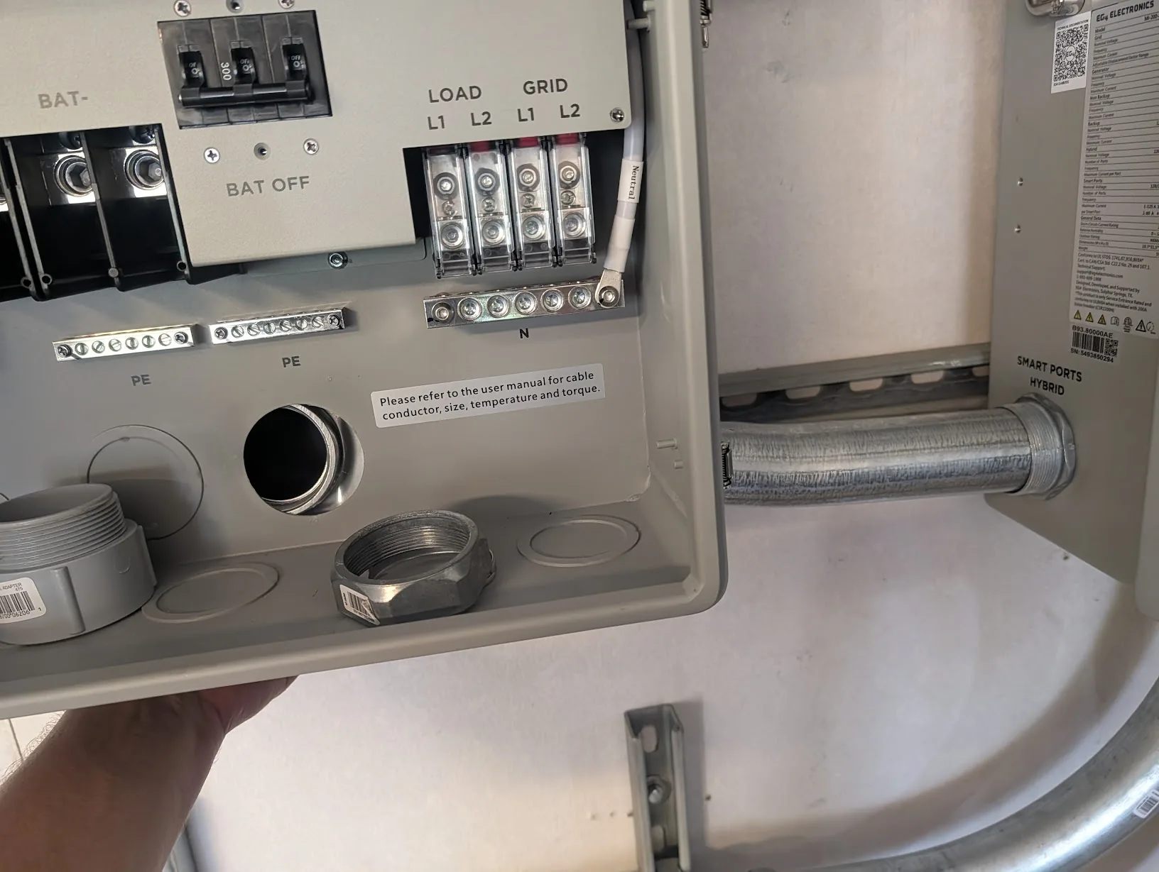
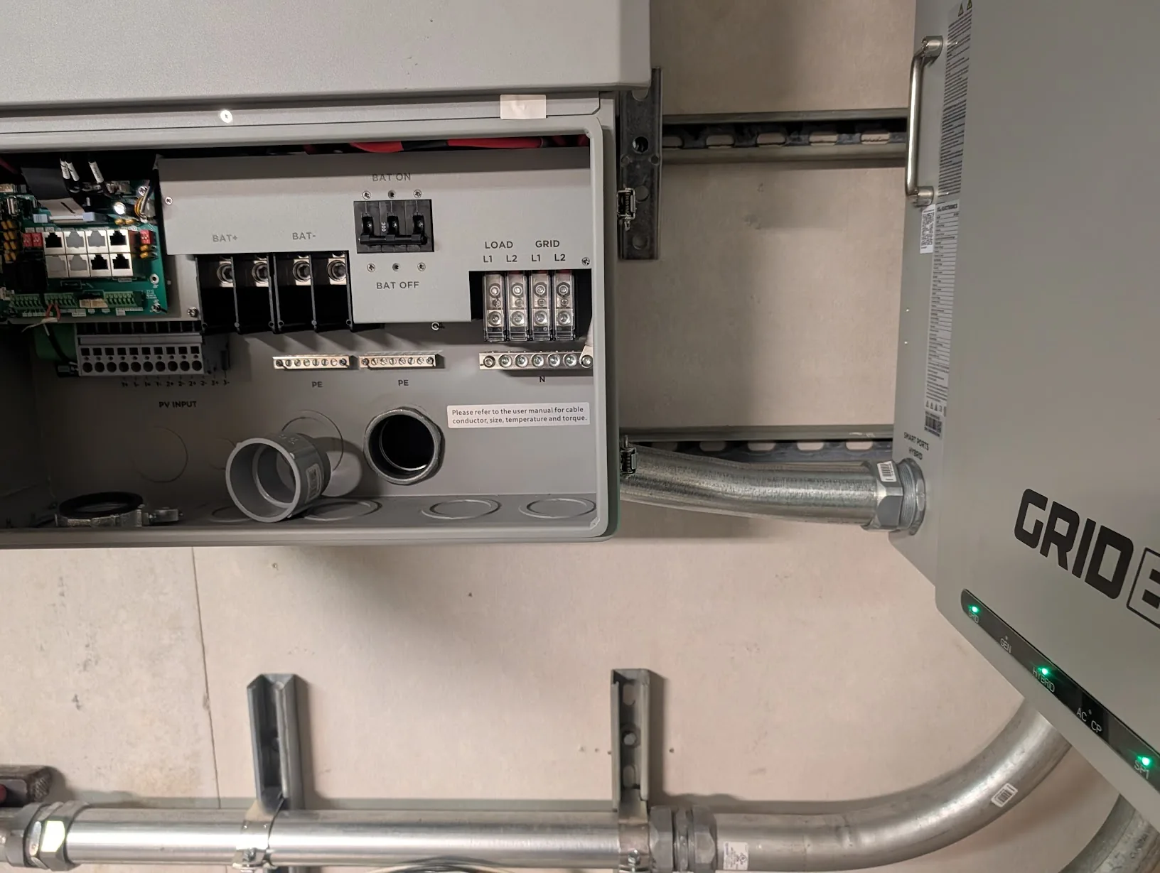
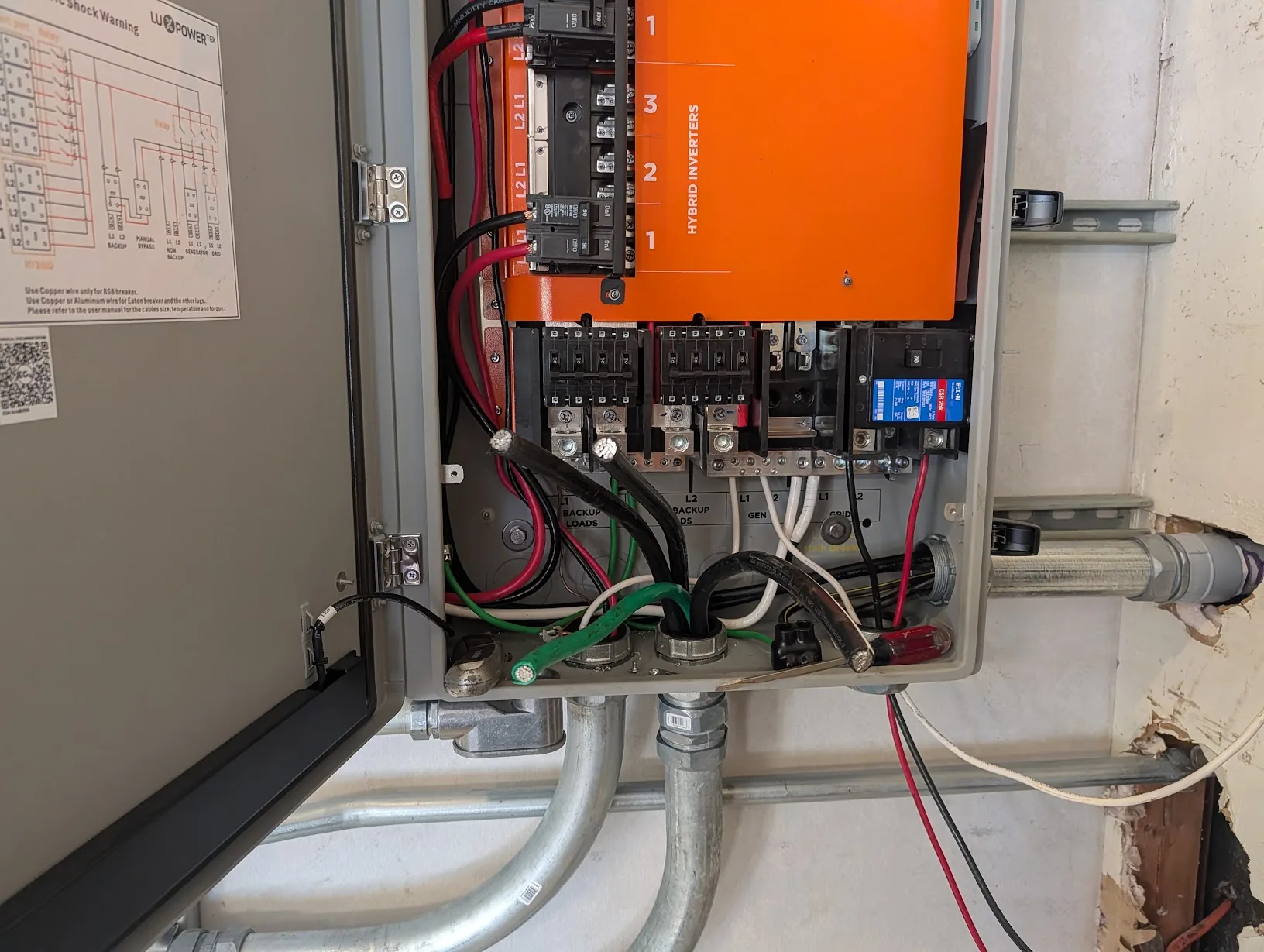
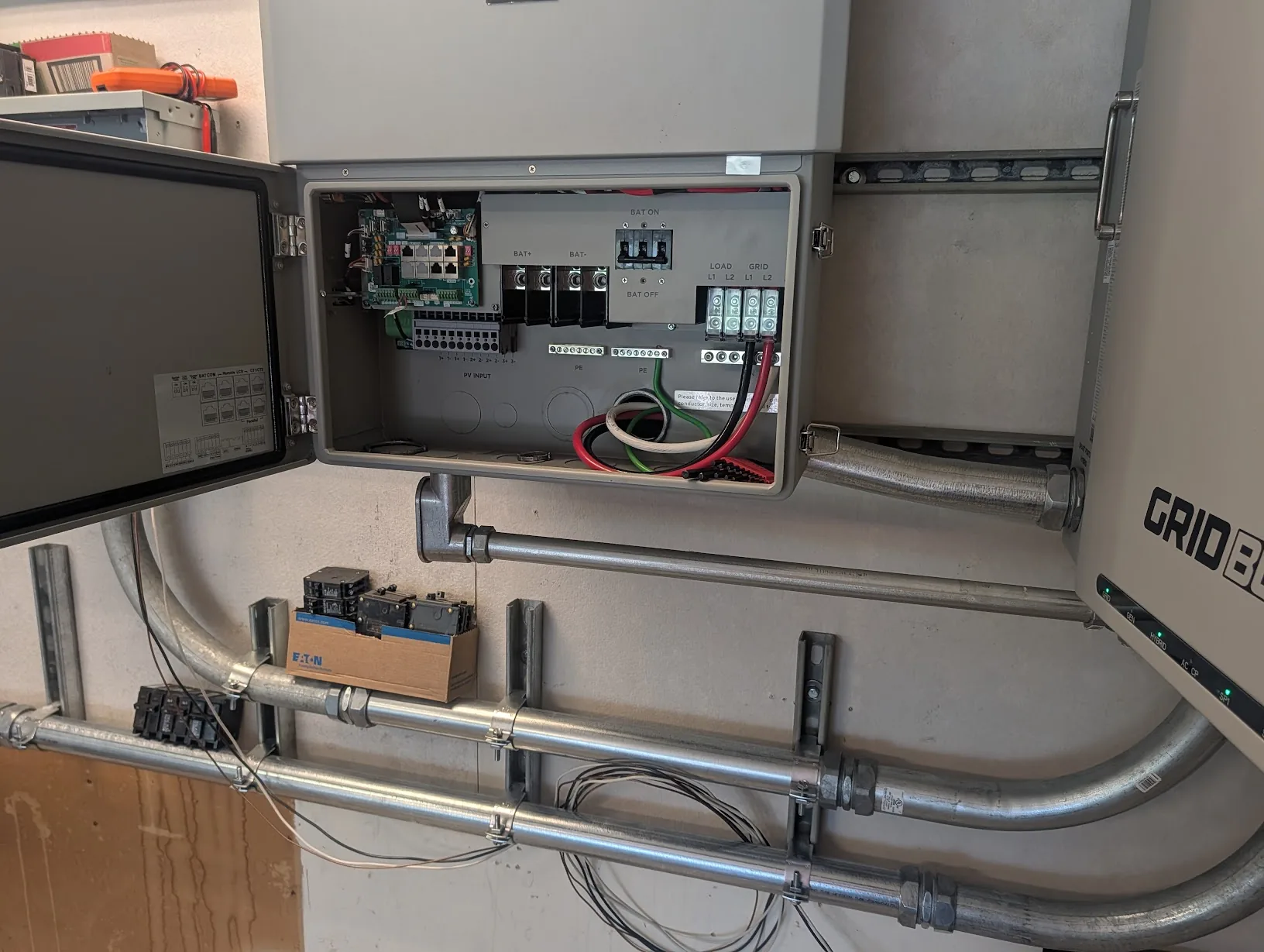
For the GridBoss side, the wiring is nearly completed. The only items left to do in here are to disconnect the incoming main power and move the conduit to instead run into the GridBoss, and to run ethernet/communications cables.
For the FlexBoss21, I pulled the cable through the rear. Don't forget to add an EGC!
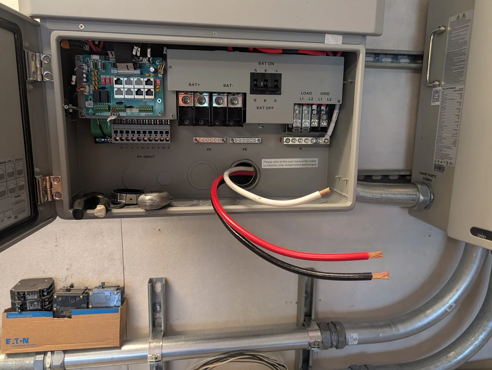
When used with the GridBoss, nothing should be connected to the load port.
Info
Notice, nothing is connected to the non-backup loads port.
My intention is to be able to run FULLY off-grid if desired. The non-backup port is ONLY active with either a grid or generator connection.
That is not desired for this installation.
Originally, I planned on using the subpanel as a "more critical" loads panel. Instead, I am now planning to use it as a load-shedding panel — when power is out and batteries start to run low, the GridBoss can switch off the entire panel to save energy.
You may also notice the small 1" conduit running out the bottom of the FlexBoss21, going to the GridBoss. This is for low-voltage communications cables.
Finishing Exterior Conduit
Almost forgot to add this section!
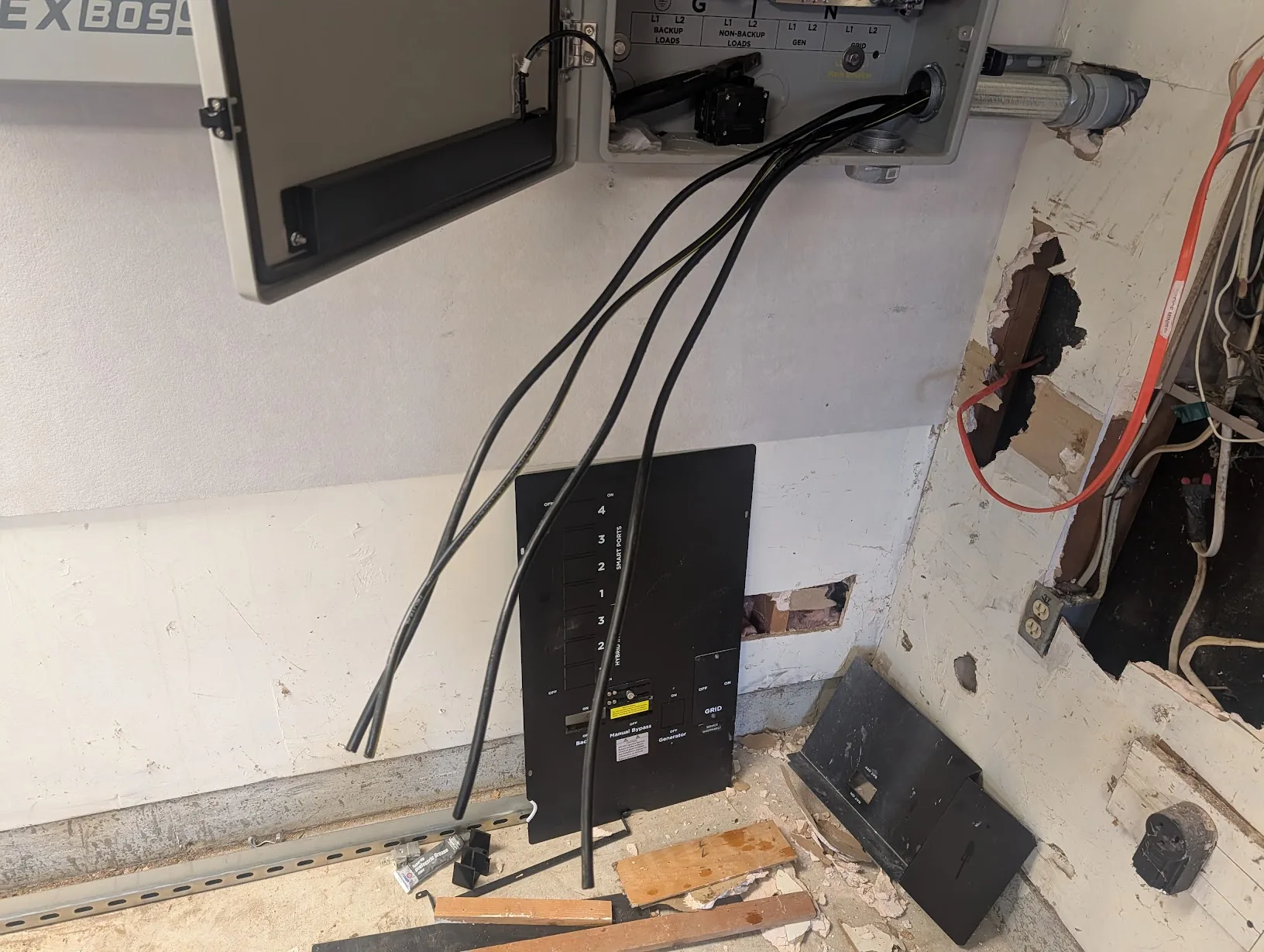
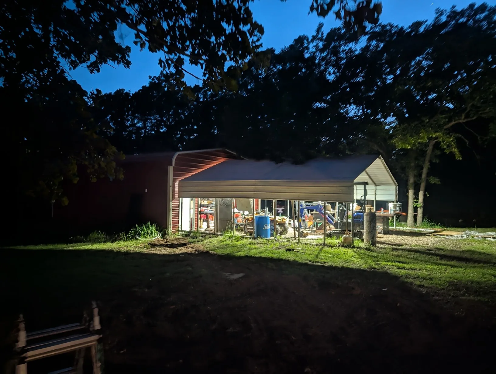
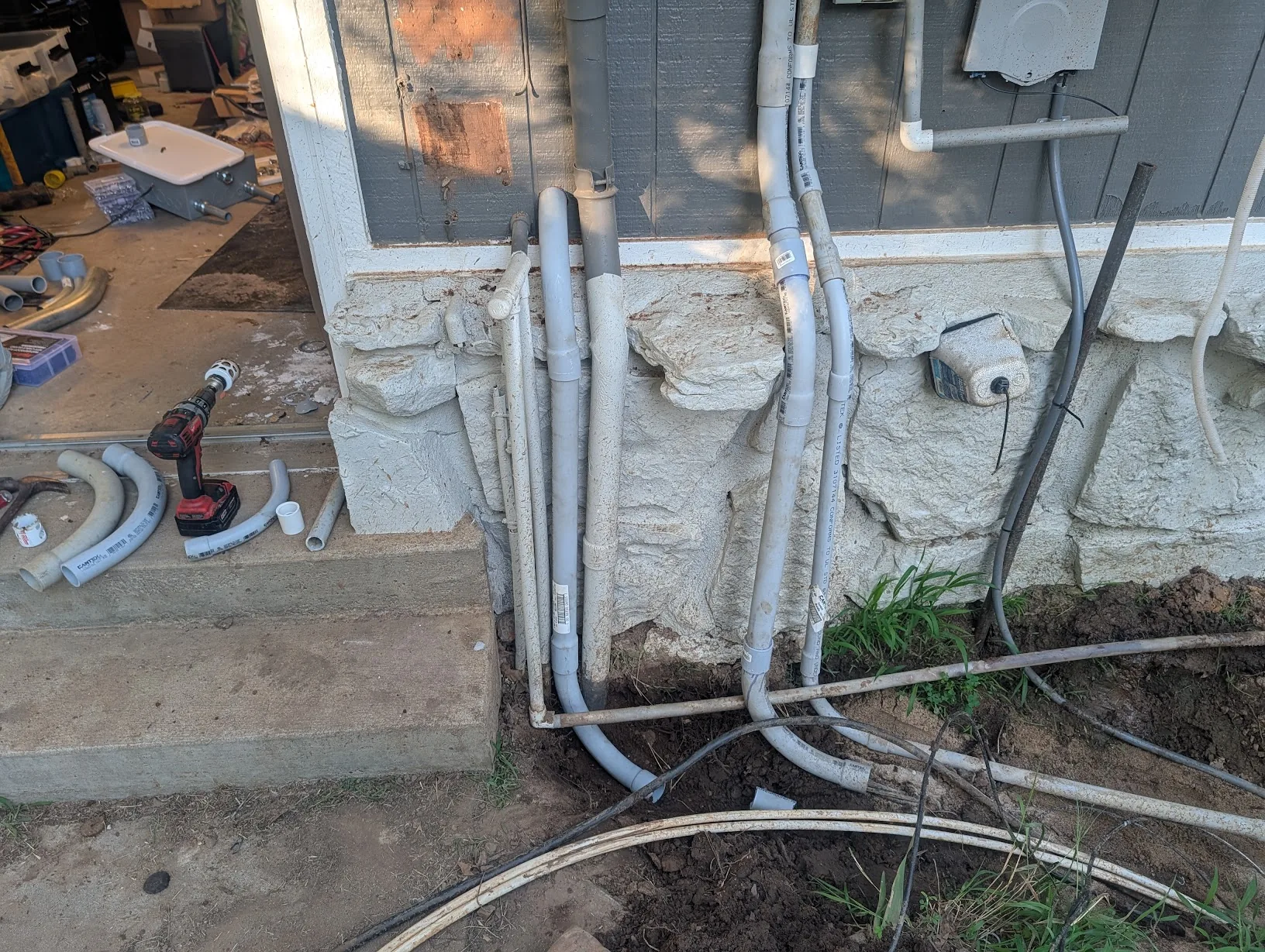
When we left off from the last part, the exterior of the house looked... roughly like this:
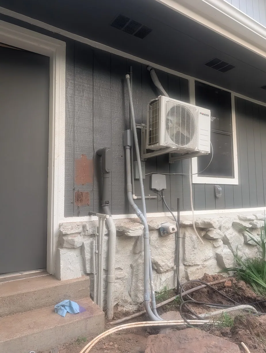
I went ahead and ran 1" conduit for the PV wiring, to the right of the existing 1.5" conduit for the shed power wire.
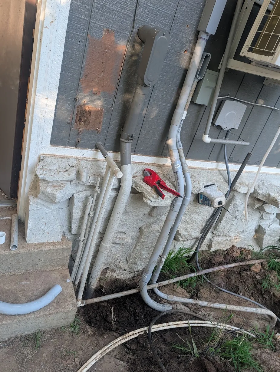
For the rest of the cables, after kicking around a few ideas, I decided to toss it all into a piece of 2" conduit hanging low on the wall.
After drilling the hole, I attached a pipe connector and screwed it down tight, with lots of silicone to prevent water from seeping inside the house.
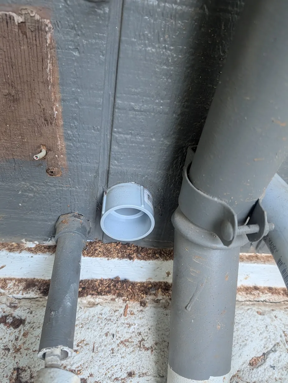
And, voila, a piece of conduit. Just need to cement everything together now.
A few hours later....
All done! And the hole has been mostly covered back up.
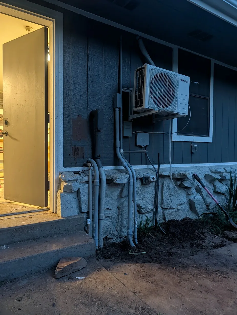
While the image is dark, you may notice there are a few things missing. The grounding rod which was previously installed here was not used at all — the main grounding connector for my house is at the pole.
So I removed this one. I also found the conduit running down the side of the house was disconnected and not in use, so I removed that as well.
For the interior side, nothing special here.
I came out the next day, added some sand, and placed a big rock in the middle to help clean this area up a bit.
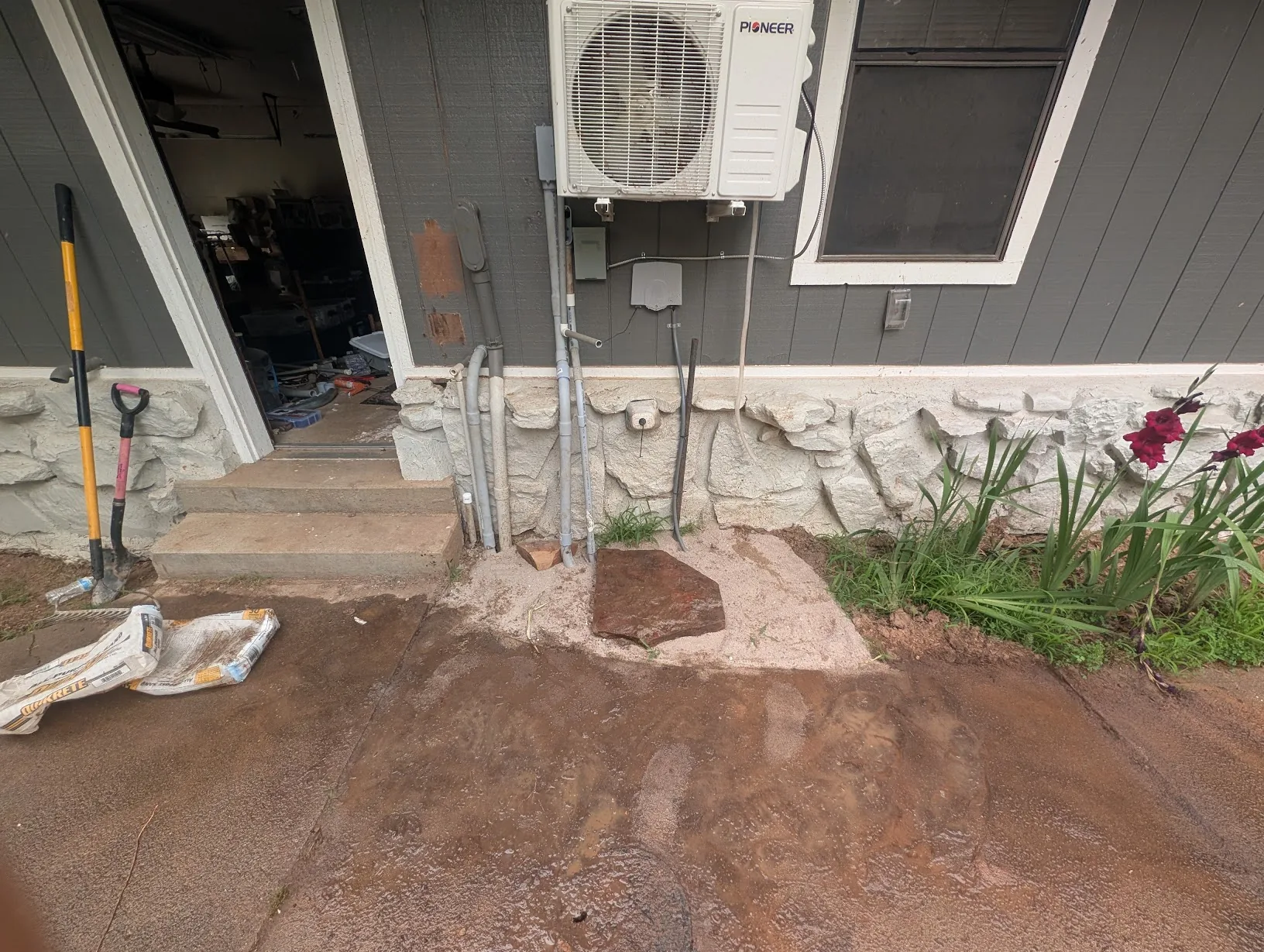
This area is very close to being done — there is still more work to do here in the future. I need to add an exterior rapid-shutdown switch, AND redo/re-route the existing incoming power cable into the GridBoss.
-
Amazon Affiliate Links Used
This post DOES include Amazon affiliate links. If you found this content useful, please consider buying the products displayed using the provided links.
You will pay the same amount as normal, however, it does provide a small benefit to me. This benefit is usually used to purchase other products and hardware for which I can review / blog about.
I do not display advertisements on this site. As such, the only compensation from this service, comes from affiliate links. I do not ask for, or even accept donations.