Aeromotive Eliminator Install
Backstory- My holley 12-1800 died, and I needed a replacement which could handle the occasional trip to work.
Info
This post was originally published in 2018, and has been adopted to this static-site from wordpress. The build has since been retired.
The shop which I purchased the 12-1800 from, was able to swap me out a new eliminator fuel pump.
After fully reading the documentation and requirements for the new pump, I determined I would need to add a sump to my existing fuel tank, upgrade the feed lines to -12AN, and implement a system for PWM control during normal driving to prevent fuel overheating.
Parts ordered:
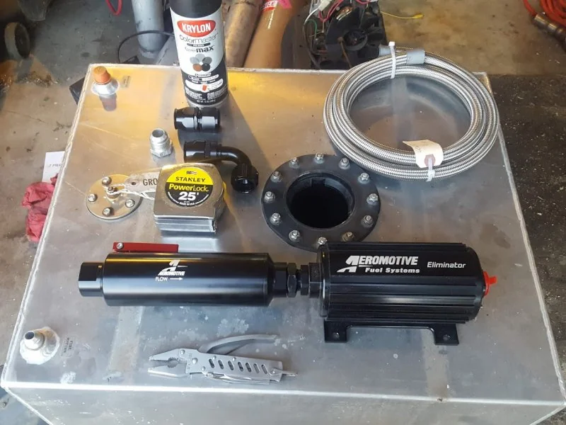 Parts needed for the new fuel pump, and filter.
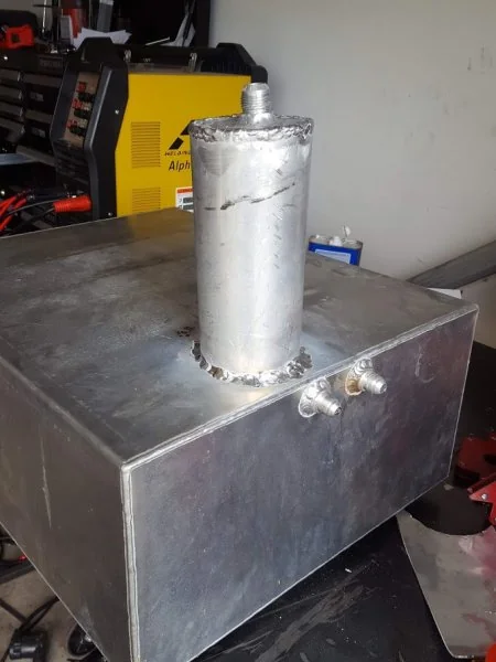 Big sump. If there is fuel in the tank, there is fuel in the sump.
For the sump- I welded on a 1 foot section of my old, broken driveshaft. Since the tank is mounted in the bed of the truck, there is more then adequate room for this.
For the PWM setup, I made a simple, stupid table in the holley EFI.
Basically, under moderate throttle, or boost, the pump goes to 100%. I have since improved.
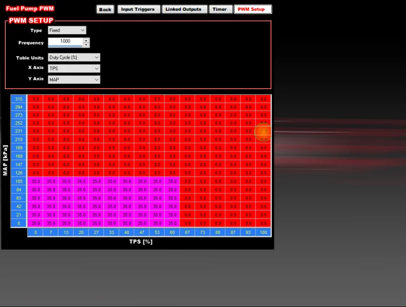 Very Simple, Stupid PWM config in the Holley.
For parts, You will need a solid state relay, and a flyback diode. Both of these parts are extremely important. A regular relay will burn up. Without a flyback diode, you will burn up your solid state relay from the inductance.
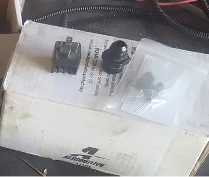
The solid state relay is important- A normal relay isn't meant to switch a PWM signal.
The flyback diode is also very important- It keeps the inductance from the pump from frying your solid state relay.
At the current time, I am using this relay:
https://www.amazon.com/gp/product/B000VU5FPE
One note- check whether your relay is normally open, or normally closed. In my case- this one is normally open. So, a 100% PWM signal, turns the pump off. 0% PWM signal, is max.
For the flyback diode, I used one of these:
https://www.amazon.com/gp/product/B0056RHMCG
It is wired from the Pump (+) to the (-) terminal. When a large spike is created from the pump spinning down, it "eats" the excess current.
I did not remember to take pictures of the wiring diagram, or the wiring.
One year follow-up
After one year of street driving- I can say this setup has held solid with no issues. I did adjust the PWM config in the holley to not be based on TPS.