Converting a fan, into a smart fan!
Introduction
Info
This post was originally published in 2020, and has been adopted to this static-site from wordpress.
I have been increasingly automating bits and pieces around my house. One piece that I still have to manually touch a few times a day, is my fan...
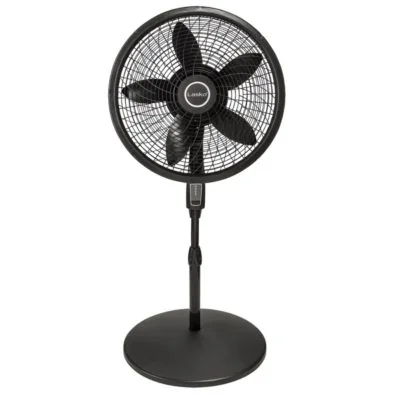
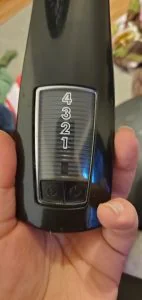
What my fan looks like.
I can think of a few uses for automation here.
- My bedtime routine can make sure its automatically turned on.
- I can integrate it into my "work from home" routine.
- I can make it automatically turn off when I get out of bed in the morning.
So- now that the decision has been made, lets get started!
What you will need
A soldering iron
Since we will be removing the existing circuitry and adding a new circuit board, a soldering iron will allow strong connections to be made. We don't want a 20amp 110v wire hanging around.
One option, is a ~100$ soldering station on Amazon, which includes a hot air gun, soldering iron, AND DC Power Supply.


However- I was not aware those existed when I picked my soldering iron a few years back.
A wireless/mqtt relay
I used a sonoff basic. There are many other alternatives you can use instead!


The price was very reasonable, for around 6$ each, and rated at 10amps.
A USB UART/Serial interface
I will be using this one, which I picked up for 10$.


Headers or loose wires to solder on.
I am going to solder on headers to make future reprogramming easy. However, if you are cheap, you can just solder on some wires temporary.... just be very careful while flashing the device.


Step 1. Flash ESPhome onto the sonoff
While you CAN use the built-in firmware, or you can instead use tasomoto, I am choosing to use ESPHome for this device.
You can find specific documentation from esphome, on their site.
https://esphome.io/devices/sonoff_basic.html
Step 1. Solder on UART headers.
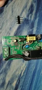
The 4 open holes in the middle, are the UART pins.
This is after I have soldered pins into the holes. You can clearly see the markings on the back.
My soldering isn't the best in the would. I am NOT Louis Rossman!!
After your headers are soldered on, you need to connect to your PC using a UART cable and flash ESPHome onto your device.
To get started, here are two basic commands.
-- Install ESP Home
pip install esphome
-- Pick a directory to store your configs.... don't lose this.
cd c:\my_esphome_folder
-- The wizard will walk you through the process of creating a basic configuration.
esphome bedroom_fan.yaml wizard
--This command will flash to your device
esphome bedroom_fan.yaml run
Here is the final configuration file I came up with. Passwords and other sensitive information have been removed or replaced.
esphome:
  name: bedroom_fan
  platform: ESP8266
  board: esp8285

wifi:
  ssid: "Wireless"
  password: ""
  domain: "xtremeownage.com"
  fast_connect: True
  power_save_mode: none
  manual_ip:
    static_ip: 10.234.1.247
    gateway: 10.234.1.1
    subnet: 255.255.255.0

  # Enable fallback hotspot (captive portal) in case wifi connection fails
  ap:
    ssid: "Bedroom Fan Fallback Hotspot"
    password: ""

captive_portal:

# Enable logging
logger:

# Enable Home Assistant API
api:
  password: ""

ota:
  password: ""

binary_sensor:
  - platform: gpio
    pin:
      number: GPIO0
      mode: INPUT_PULLUP
      inverted: True
    name: "Bedroom Fan Button"
    on_press:
      - switch.toggle: relay

switch:
  - platform: gpio
    name: "Bedroom Fan"
    pin: GPIO12
    id: relay

status_led:
  pin:
    number: GPIO13
    inverted: yes
Here is a image of me flashing the device.
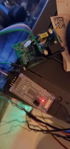
Flashing the sonoff with ESP Home
Step 2. Modifying the fan
The next part, was to integrate this into the fan. Originally- i was going to hook up the LED.. however, in the process of discovering the LED on the sonoff is inverted, I cooked the first board, and then decided to skip the LED.... mainly, because I like it pitch dark while I sleep.
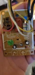
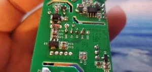
Circuit board for the fan.
If, I was an electrical engineer- I would have likely instead used a nodemcu, and attached GPIOs to all of the possible fan speed combinations. However- That is above my knowledge, so I opted for on/off at high speed only... since this is the only thing I use the fan for.
To do this- I just needed to solder wires from the power button switch, to the sonoff's switch. This is the red/blue wires below.
I clipped all of the components off of the circuit board, and put my really bad hot-glue skills to use.
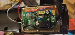
This is the new sonoff board glued on top of the old circuit board, with its components removed.
At this point, I was able to reassemble the fan... and magically it works. After enabling the ESP Home Integration in home assistant, the fan worked exactly as expected, without issues.
Do note- in the process of this- I did manage to...
- Burned up a sonoff.
- had to disassemble and reassemble multiple times, due to wires hitting the sonoff's button.
So- if you attempt this and fail... don't give up. Try again...
I can say the end result was defiantly worth it. I can now control my fan through scenes and automations... the days of having to manually walk over and turn my fan on/off are over!
Just- be careful around 110v. It can and WILL kill you.
My next custom project, will be to convert my Garage door, into a "Smart" garage door.
Additional Sources
Here are a few of the additional references I used while completing this project:
- https://esphome.io/guides/getting_started_command_line.html
- ESP Home Getting Started. You need this to flash your device.
- https://esphome.io/components/wifi.html
- ESP Home Wifi Configuration Options
- https://esphome.io/components/switch/index.html
- ESP Home Switch Configuration Options
- https://esphome.io/devices/sonoff_basic.html
- ESP Home Sonoff Basic Guide