FADD - Feline Area Denial Device
My wife presented me with a unique challenge recently.
"The cats keep getting on top of the kitchen table, and getting hair everywhere!"
So- the logically minded person I am- I decided to build a home-assistant integrated device for keeping cats off of the table!
I present to you, the FADD. Feline Area Denial Device!
⚡️ Shock Risk
This project can shock you. ⚡️🤕🚑️
🔥 Fire Hazard
This project presents a potential fire hazard. Do not use this around anything flammable. Do not use this unsupervised. 🔥🚒
Danger
This project should not be used around pets or small children. 🐈️🐕️🤸
Caution
Make sure you read the disclaimers!
Also- you probably should not build this.
The concept
The concept is simple. I will use Frigate, combined with a Google Corral TPU, to detect when the cats are near the kitchen table.
When the kittys are either on, or near the kitchen table, I will trigger a taser like device.
This taser like device, is not intended to shock or physical harm anyone, and is mounted away from kids and pets.
The idea- the taser-like sound, will scare away the cats.
The End Result
Build / Assembly
Software Used
- Home Assistant
- This is my home automation platform of choice.
- ESPHome
- This is the firmware I typically run on my ESP-based projects
- Frigate
- I am leveraging Frigate, combined with a Google Coral TPU to detect objects.
Parts needed
- "High-Voltage" Generator.
- Amazon
- I ended up picking up 5 of these, for 20$ shipped, or 4$ each. However, you can buy just a single module for 10$.
- This converts the incoming 5v, into around 40kv. (Ignore the 400kv claim... that is false. But, based on my math, it does generate 40-50kv)
- 5v 3 amp power supply
- Amazon
- I suppose you could use a normal 2amp USB brick, however, I opted for this 3 amp power supply instead.
- ESP32
- Amazon
- I had a bunch of ESP32s laying around, however, you COULD instead use a ESP8266 or D1 Mini for a cheaper.
- I went with the ESP32, to also try out the new Esphome Bluetooth Proxy functionality.
- But- for this project, the ESP32 offers no additional required functionality over what a ESP8266-based module provides.
- Some form of enclosure
- Amazon
- A few years back, I picked up a bunch of these ABS plastic enclosures. They occasionally come in handy for projects exactly like this.
- I recommend a non-conductive enclosure, due to the high-voltages here.
- MOSFET OR Relay module
- MOSFET - Amazon
- I went with a MOSFET over a traditional relay, because I wanted to see if I could pass a PWM signal to the step-up coil to alter the frequency of the sound generated.
- I will note, I was unsuccessful in doing so. However- these little modules do work quite nicely. You can substitute a relay instead, with minor changes to wiring
- Relay - Amazon
- DO note- whichever solution you choose will need to be able to be triggered via 3v signal.
Overall, I'd estimate I spent around 50$ for this project, HOWEVER, I have enough components to build 5 of these things, if I wanted.
OTHER Hardware Used
- Reolink E1
- I always recommend using a hard-wired POE camera over a wireless camera. However, this is a temporary project, which will not be permanently attached.
- But, for 30$ a piece, these wireless cameras do come in quite handy for quick POC, testing, and other purposes.
- For permanent mount cameras, my current recommendation is the Reolink RLC-520
- Google Coral USB Accelerator
- IF you can get your hands on one of these, it greatly accelerates how quickly objects can be detected.
- It also allows you to perform object detection, while hardly using CPU resources.
Wiring
Please forgive my drawing. However, the wiring of this project is extremely simple.
From your 5V power supply-
Connect positive to:
- VIN plug of your selected ESP device. (NOT the 3.3v link!!)
- Positive input of your MOSFET or relay.
Connect negative/ground to:
- GND pin of your selected ESP device. There are a few GND pins, pick your favorite.
- Negative input of your MOSFET or relay.
Connect the OUTPUTs of your MOSFET, to the inputs of the "high-voltage generator" (The side with a blue wire)
Finally, connect a GPIO from the ESP to the MOSFET. I went with GPIO12. However, as long as you don't choose a reserved GPIO, you should be fine.
In hindsight- I should have used GPIO16 - 33 as there is nothing special about those pins, and they are capable of generating a PWM signal, if you want to experiment.
Connect the GPIO to the TRIG/PWM input of the MOSFET.
Assembly
For assembly, I only used a few tools:
- Soldering iron- for soldering wires to pins / connections.
- Hot Glue Gun - To hold everything in place.
- This is a cheap, quick POC project. Hot glue will work just fine here.
- A drill
- Used to make a hole for the DC 5v PIN.
First, solder all of the connections noted in the previous step.
Next, I drilled a hole for the DC 5v PIN, and then used hot glue to hold the plug into place.
Finally- I carefully placed the remaining components inside of the case.
After careful organization, I snapped the lid into place, and soldered the high-voltage leads into a mostly-fixed position.
Do note, altering the distance between the leads will alter the sound/frequency which is emitted.
The only concern I would be aware of during assembly- Try to keep the high-voltage leads as far away from the ESP as possible! Otherwise, you may end up zapping it.
Danger
Make sure to affix the high-voltage leads into a position where the ARC is NOT near anything flammable OR conductive.
This CAN present a fire / shock risk. You have been warned.
The last step- is to place the unit somewhere secure, away from children and pets.
Esphome Firmware
For this project, I am using Esphome. It supports all of the functionality I need, and it easily integrates with Home Assistant, and MQTT, allowing me to easily automate it.
Here is the configuration file I am using:
substitutions:
  devicename: "cat_zapper"
  friendly_name: "Cat Zapper"
  ip_address: 10.1.2.3
  gateway: 10.1.2.1
  <<: !include secrets.yaml

<<: !include common/common.yaml

esphome:
  name: ${devicename}
  friendly_name: ${friendly_name}

esp32:
  board: esp32dev
  variant: esp32

sensor:
  # Wifi Signal
  - <<: !include common/sensor-wifi-signal.yaml

  # Uptime
  - <<: !include common/sensor-uptime.yaml

button:
  # Restart Button
  - <<: !include common/button-restart.yaml

  # Safe Mode Button
  - <<: !include common/button-safemode.yaml

  - platform: output
    output: zap
    name: "Zapper"
    duration: 400ms

output:
  - platform: gpio
    pin: GPIO12
    id: zap

# Uncomment if you would like a web interface
# web_server:
#   port: 80
Regarding the contents of the "common" files, I have those documented here: ESPhome Common. I use this include functionality, to keep my configuration files cleaner, and to avoid repeating the same configuration in multiple locations.
For my configuration, I used a Button to trigger this device. This uses the generic output button, which allows me to trigger a GPIO output for a determined amount of time.
You can alter the duration of the "Zaps" by adjusting the duration parameter in the above configuration.
Info
The reason I am leveraging a generic output button, instead of a GPIO switch, is to control the duration during which this device is active. I wanted to greatly reduce the possibility of this device getting stuck in an "ON" position, which would greatly elevate the risk of fire.
The Automation
Frigate Configuration
After configuring this camera in Frigate, I had a video stream.
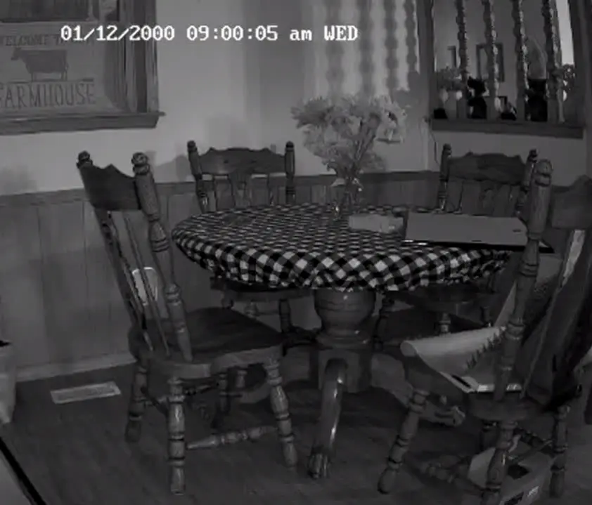
However, I really only care when there is a cat on or near the kitchen table. I don't want to waste resources detecting people walking near the table.
So, I created a motion mask, and masked off all of the areas I do not care about. This left me with the following view:
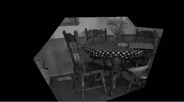
Do note, this is a color camera. However, since the room is currently uninhabited and dark- it is in "night vision" mode, which is black and white only.
After everything was completed, here is what I was left with:
objects:
  filters:
    cat:
      # I lowered the score for detecting cats slightly, to improve detections.
      min_score: 0.4
      threshold: 0.6


cameras:
  kitchen:
    detect:
      width: 640
      height: 354
      fps: 7
    ffmpeg:
      inputs:
          # This path is specifically for a Reolink E1. As well, I am using the sub-stream for detection.
        - path: rtsp://YourUser:YourPassword@10.1.2.3:554/h264Preview_01_sub
          roles:
            - detect
            - record
    motion:
      mask:
        - 502,304,366,354,640,354,640,277,640,181,640,0,0,0,0,354,202,354,115,206,173,134,227,61,442,58,473,93,569,101
    zones: # I also created a specific zone, for the areas I am wanting to detect cats.
      zone_0:
        coordinates: 0,354,329,354,475,354,530,333,581,108,447,39,269,40,0,42
    objects:
      track:
        - cat
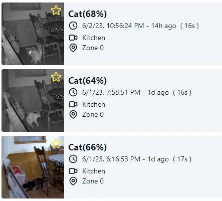
With these settings, over the last few days, I have gotten extremely accurate detections.
Home Assistant Configuration
I will be adding the actual automation inside of Home Assistant. The automation is actually quite simple.

alias: Cat Taser
description: Fire the lasers
trigger:
  - type: occupied
    platform: device
    device_id: 94e0766834ecff68ee26b72f231499de
    entity_id: binary_sensor.zone_0_cat_occupancy
    domain: binary_sensor
condition:
  - condition: state
    entity_id: input_boolean.mode_vacation
    state: "off"
action:
  - repeat:
      while:
        - condition: state
          entity_id: binary_sensor.kitchen_cat_occupancy
          state: "on"
      sequence:
        - device_id: 914217f5ad93dc688d9d6f3ea86e1b29
          domain: button
          entity_id: button.cat_zapper_zapper
          type: press
        - delay:
            hours: 0
            minutes: 0
            seconds: 5
            milliseconds: 0
mode: single
- When
binary_sensor.zone_0_cat_occupancyturns on (ie. there is a cat inside of zone 0) - AND, I am not on vacation
- THEN, Press the "zapper" button every 5 seconds, until there is no longer a cat inside of zone 0.
That's it!
Does it work?
I WOULD have more videos, however, after deploying this device- the first two videos didn't come through with any sound. And, after the 3rd detection- the cats have not returned to the kitchen table.
Overall, I would call this a success... as not a single cat hair has been found on top of the kitchen table since deployment.
And- this can be easily repurposed for other areas of the house.
Disclaimers
⚡️ Shock Risk
This project can shock you. ⚡️🤕🚑️
🔥 Fire Hazard
This project presents a potential fire hazard. Do not use this around anything flammable. Do not use this unsupervised. 🔥🚒
Danger
This project should not be used around pets or small children. 🐈️🐕️🤸
Caution
Make sure you read the disclaimers!
Also- you probably should not build this.
Amazon Affiliate Links Used
This post DOES include Amazon affiliate links. If you found this content useful, please consider buying the products displayed using the provided links.
You will pay the same amount as normal, however, it does provide a small benefit to me. This benefit is usually used to purchase other products and hardware for which I can review / blog about.
I do not display advertisements on this site. As such, the only compensation from this service, comes from affiliate links. I do not ask for, or even accept donations.